Sheet processing apparatus with branching paths for post-processing

a post-processing and processing apparatus technology, applied in the direction of thin material processing, printing, article delivery, etc., can solve the problems of larger size and higher cost of the apparatus, and achieve the effect of preventing the decline of throughput, reducing the size of the apparatus, and reducing the damage of the sheet by abutting

Inactive Publication Date: 2009-12-29
CANON KK
View PDF34 Cites 10 Cited by
  • Summary
  • Abstract
  • Description
  • Claims
  • Application Information

AI Technical Summary

Benefits of technology

[0008]It is hence an object of the invention to provide an inexpensive sheet processing apparatus of small size, not lowered in throughput of the connected image processing apparatus.
[0010]According to the invention, by aparting the discharge roller pair from each other, the sheet can be stacked in a state of sheet front end projecting from the discharge roller pair, and therefore not only the space for temporarily placing the sheet can be used as the conveyance path before discharge roller pair, but also the space above the stacking tray can be used as temporary stacking space. As a result, unlike the prior art, it is not required to have a wide space for placing the sheets temporarily in the conveyance path before the discharge roller pair, and therefore decline of throughput can be prevented without increasing the size of the apparatus. Besides, abutting of front end is not required at the time of temporary placing, sheet damage by abutting of front end can be prevented. Besides, jamming by sheet buckling due to abutting of front end is avoided, and a product of high reliability can be provided. When superimposing the second sheet, the second sheet is not stopped temporarily, and jamming of paper space between the second sheet and a third sheet is avoided, so that a sufficient aligning process time can be reserved.

Problems solved by technology

Or as disclosed in JP-A No. 1-127556, by stopping a first sheet conveyance roller, a first sheet is stopped before stacking tray discharge roller, and when the end of second sheet reaches before discharge roller pair by second sheet conveyance roller, by driving the first sheet conveyance roller, two sheets are conveyed simultaneously, and two sheets in superimposed state are discharged onto stacking tray, and even in such configuration, enough space for completely holding the first sheet within the conveyance path is required, and the apparatus is larger in size and higher in cost.

Method used


Image

  • Sheet processing apparatus with branching paths for post-processing
  • Sheet processing apparatus with branching paths for post-processing
  • Sheet processing apparatus with branching paths for post-processing

Examples


first embodiment

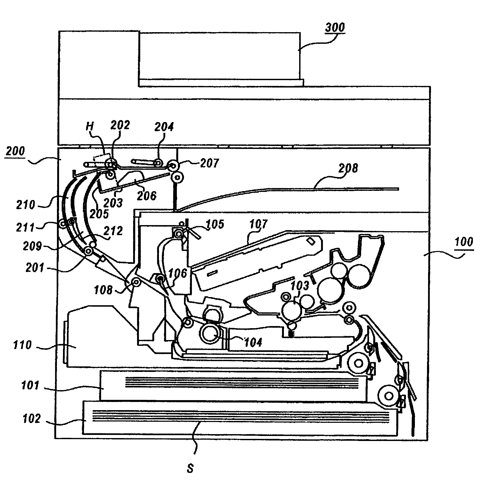
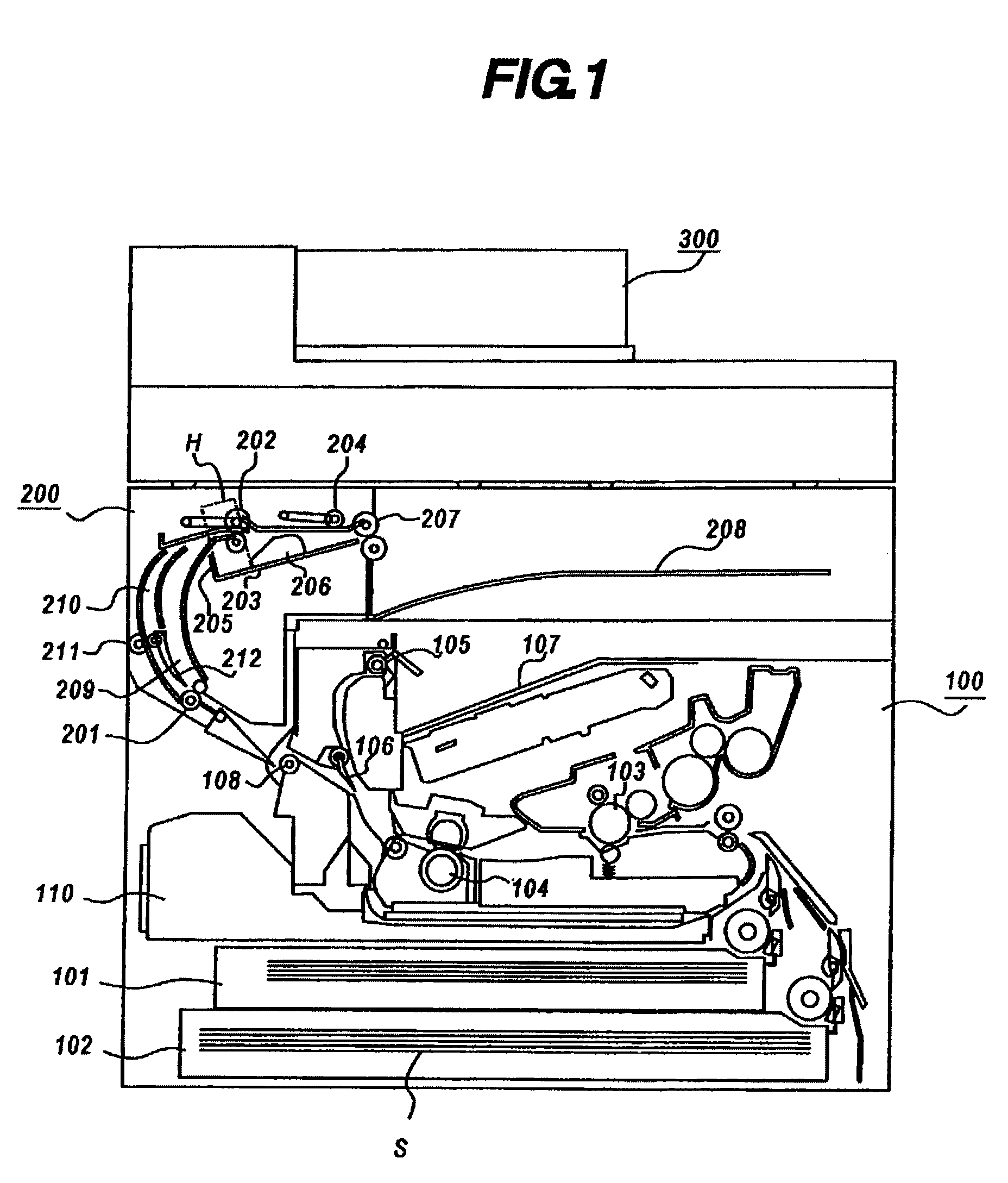
[0032]FIG. 1 is a schematic sectional view of image processing apparatus having a sheet processing apparatus according to a first embodiment. The image processing apparatus on the whole shown in the drawing is an internal discharge type configuration in which an image reading apparatus 300 is disposed above an image forming apparatus 100, and sheets on which images are formed are discharged into a space formed between the image forming apparatus 100 and image reading apparatus 300, and a sheet processing apparatus 200 can be installed in this space. The image forming apparatus 100 receives image information or print signal and the like sent directly from a computer connected thereto or via network of LAN or facsimile, or image information read by the image reading apparatus 300, and forms images on sheets by specified image process based on such information, and discharges sheets.

[0033]First, referring to FIG. 1, the configuration of the image forming apparatus 100 is explained alon...

second embodiment

[0049]A second embodiment of sheet processing apparatus of the invention is described. FIG. 4 is a diagram explaining the configuration of sheet processing apparatus of the second embodiment, and FIGS. 5(a) and 5(b) is a diagram explaining the operation of sheet processing apparatus, and same parts as in the first embodiment are identified with same reference numerals, their explanation is not described.

[0050]This embodiment is different from the first embodiment in the shape of the conveyance path from first path roller 201 to discharge roller pair 202.

[0051]As shown in FIG. 4, a sheet processing apparatus 400 of the embodiment is disposed in an upper and side portion of image forming apparatus 100, and is designed to discharge the sheet bundle after post-processing to outside of the machine. A first path 401 is nearly straight, and a second path 402 is curved and disposed closely to the first path 401. In this embodiment, after images are formed in the image forming apparatus 100,...

third embodiment

[0055]A third embodiment of sheet processing apparatus of the invention is described. FIG. 6 is a diagram explaining the configuration of sheet processing apparatus of the third embodiment, and FIG. 7(a) to 7(e) is a diagram explaining the operation of sheet processing apparatus, and same parts as in the first embodiment are identified with same reference numerals, their explanation is not described.

[0056]This preferred embodiment is different from the first embodiment in the aligning means in a direction orthogonal to sheet conveying direction.

[0057]In a sheet processing apparatus 500 shown in FIG. 6, a lateral aligning roller 501 for aligning sheets in a direction orthogonal to sheet conveying direction is provided beneath discharge roller pair 202 and at the upstream side in sheet conveying direction. In this embodiment, the lateral aligning roller 501 moves the sheet in a direction orthogonal to sheet conveying direction, but the lateral aligning roller 501 may have an angle aga...


PUM

PropertyMeasurementUnit
lengthaaaaaaaaaa
sizeaaaaaaaaaa
curvatureaaaaaaaaaa

Abstract

A sheet processing apparatus which perform a process to sheets comprising a stacking tray on which stacks the sheets to be performed a process; a discharge roller pair; a first path in which conveys a sheet to the discharge roller pair, shorter than the length of the minimum sheet size being conveyed in the sheet conveying direction; a second path branched from the first path and meeting with the first path at the upstream side in the sheet conveying direction of the discharge roller pair; and a path switching member, wherein a first sheet conveyed while processing the sheets on the stacking tray is guided into the first path by the path switching member, and when the front end of the first sheet projects from the discharge roller pair, the discharge roller pair is apart from each other and the first sheet is held in the first path, and the path switching member is changed over, and a second conveyed sheet is guided into the second path, when the front end of the second sheet projects from the discharge roller pair by a prescribed length, the discharge roller pair is closed to each other, and the first and second sheets are discharged onto the stacking tray in superimposed state by the discharge roller pair.

Description

BACKGROUND OF THE INVENTION[0001]1. Field of the Invention[0002]The present invention relates to a sheet processing apparatus connected to an image forming apparatus for collecting, aligning and post-processing the sheets discharged from the image forming apparatus, and more particularly to an apparatus having a stacking tray for stacking and aligning a plurality of sheets temporarily.[0003]2. Description of the Related Art[0004]Hitherto, the sheet processing apparatus is connected to an image forming apparatus, for conveying the sheets discharged from the image forming apparatus, aligning and sewing, and moving the sewn sheet bundle to a stacking tray. At this time, while processing the sheet bundle, next sheet bundle cannot be sent into the stacking tray, and the throughput is lowered. To solve the problem of throughput decline, it has been attempted to produce a post-processing time by temporarily superimposing and stacking two sheets before the nip section of the roller for disc...

Claims


Application Information

Patent Timeline
Patent Type & Authority Patents(United States)
IPC IPC(8): B65H39/10
CPCB42C1/10B65H29/58B65H31/3027B65H2301/42262B65H2404/1442B65H2511/22B65H2513/50B65H2220/02B65H2220/11B65H2220/01
Inventor ATA, HIRONOBUOGATA, ATSUSHIISOBE, KENICHIROTSUJI, HIROHARU
Owner CANON KK
Why Eureka
Try Eureka