Fuel cell having stack structure

a fuel cell and stack technology, applied in the field of stack structure fuel cells, can solve the problems of non-uniform distribution of the wet state of the electrolyte membrane, non-uniform distribution of the electric power generation performance of the unit cell, etc., and achieve the effect of suppressing the electric power generation performance of the fuel cell and likely reducing the electric power generation performan

Inactive Publication Date: 2009-12-29
TOYOTA JIDOSHA KK
View PDF19 Cites 1 Cited by
  • Summary
  • Abstract
  • Description
  • Claims
  • Application Information

AI Technical Summary

Benefits of technology

[0020]With the configuration, in the fuel cell having a stack structure, it is possible to obtain a sufficient area in which each of the aforementioned reaction occurs at the portion where the electric power generation performance is likely to decrease. Accordingly, it is possible to suppress a decrease in the electric power generation performance of the fuel cell even in the case where the temperature or the wet state of the unit cell is not optimal.
[0021]The catalytic ability does not necessarily need to compensate for a decrease in the electric power generation performance completely. However, the electric power generation performance of each unit cell can be made uniform by changing the catalyst ability such that a decrease in the electric power generation performance can be sufficiently compensated for.
[0025]With the configuration, in the fuel cell having a stack structure, it is possible to obtain a sufficient area in which each of the aforementioned reactions occurs at the region of each cell in which the electric power generation performance is likely to decrease. Accordingly, it is possible to suppress a decrease in the electric power generation performance of the fuel cell even in the case where the temperature or the wet state of the unit cell is not optimal.

Problems solved by technology

Also, a non-uniform distribution of the wet state of the electrolyte membrane occurs according to the temperature distribution.
Accordingly, a non-uniform distribution of the electric power generation performance of the unit cell also occurs in the fuel cell stack according to the temperature distribution and the distribution of the amount of water contained in the electrolyte membrane.

Method used


Image

  • Fuel cell having stack structure
  • Fuel cell having stack structure
  • Fuel cell having stack structure

Examples


first embodiment

[0051]the invention will be described.

[0052]First, configurations of the electrodes will be described.

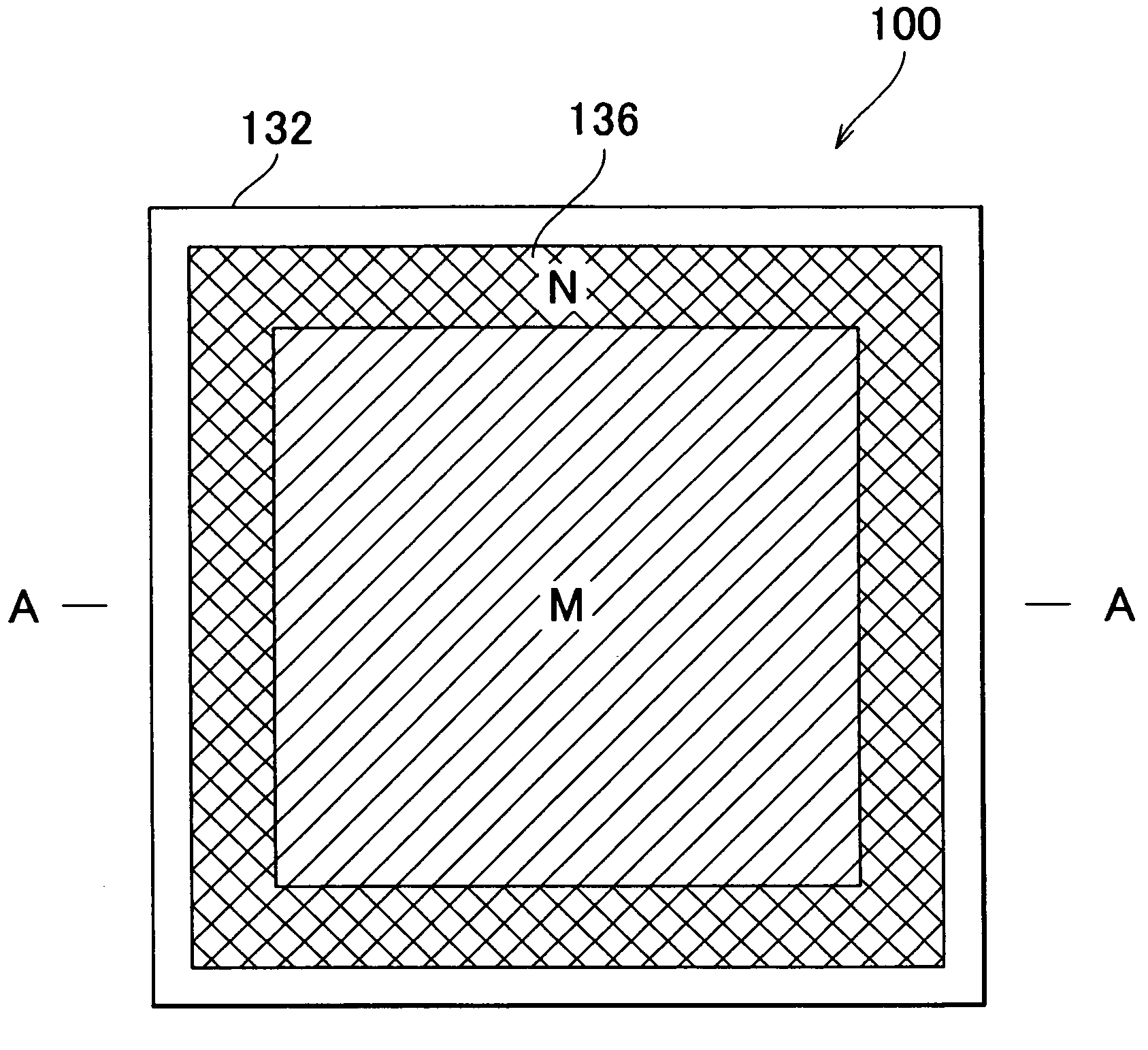
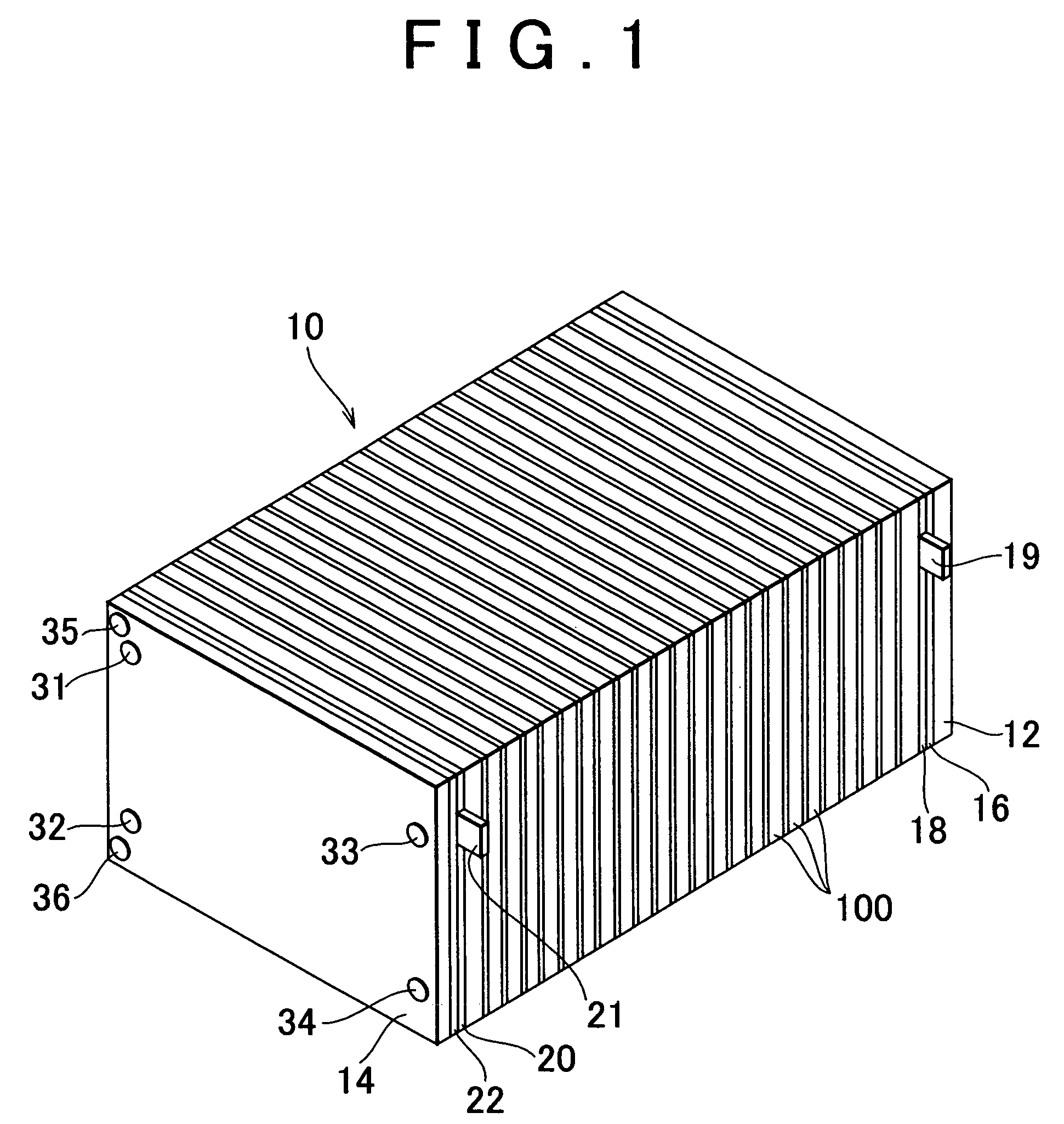
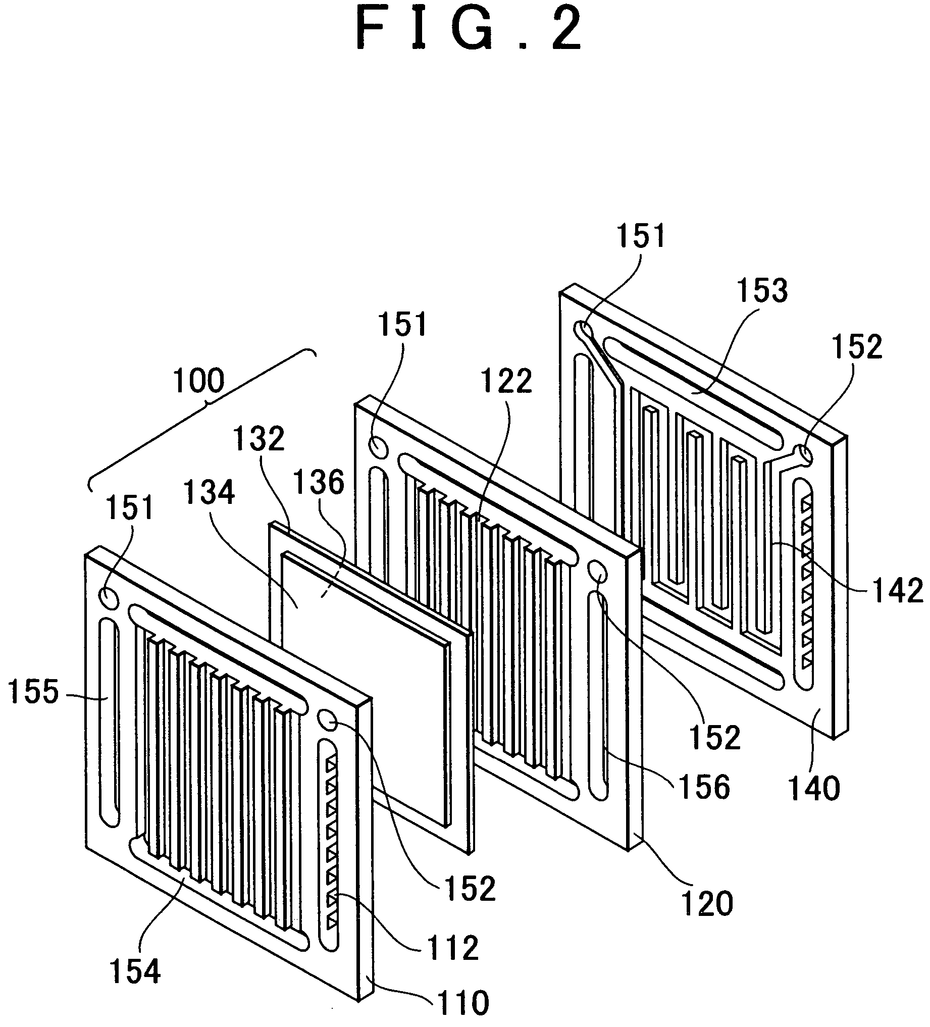
[0053]FIG. 3A is an explanatory diagram showing a configuration of the fuel cell stack 10 according to the first embodiment of the invention. FIG. 3B is a cross sectional view showing a configuration of an electrode of a unit cell positioned at the center portion of the fuel cell stack 10 (hereinafter, referred to as “center cell”). FIG. 3C is a cross sectional view showing a configuration of an electrode of a unit cell positioned at the end portion of the fuel cell stack 10 (hereinafter, referred to as “end portion cell”).

[0054]As shown in FIG. 3B, in the center cell, a catalyst layer 134a and a gas diffusion layer 134b are stacked in this order on one surface of the electrolyte membrane 132, whereby the hydrogen electrode 134 is formed. Also, a catalyst layer 136a and a gas diffusion layer 136b are stacked in this order in the other surface of the electrolyte membrane 132, whereby...

second embodiment

[0064]Hereinafter, the invention will be described.

[0065]In the first embodiment, the thickness of each catalyst layer in the center cell is different from that in the end portion cell. In the second embodiment, the specific surface area of the catalyst supported by each catalyst layer in the center cell is different from that in the end portion cell.

[0066]FIG. 5A to FIG. 5C are explanatory diagrams showing configurations of electrodes of the unit cells 100 according to a second embodiment of the invention. In the second embodiment, the thickness of each of the catalyst layers 134a and 136a in the center cell is the same as the thickness of each of the catalyst layers 134e and 136e in the end portion cell. The second embodiment is the same as the first embodiment, except that the specific surface area of the catalyst supported by each of the catalyst layers 134e and 136e in the end portion cell is larger than that of the catalyst supported by each of the catalyst layers 134a and 136...


PUM

PropertyMeasurementUnit
electromotive voltageaaaaaaaaaa
weightaaaaaaaaaa
specific surface areaaaaaaaaaaa

Abstract

A fuel cell having a stack structure is provided. The fuel cell includes plural unit cells each of which includes an anode and a cathode which are provided on both sides of a predetermined electrolyte membrane, and a catalytic layer which is provided in at least one of the anode and the cathode, and which supports a catalyst for promoting an anode reaction or a cathode reaction, the plural unit cells being stacked to form a stack structure. In the fuel cell, the plural unit cells include a unit cell including a catalyst layer supporting a catalyst which is different from catalysts supported by catalyst layers of other unit cells in at least one of type, weight, and specific surface area.

Description

INCORPORATION BY REFERENCE[0001]The disclosure of Japanese Patent Application No. 2003-376409 filed on Nov. 6, 2003, including the specification, drawings and abstract is incorporated herein by reference in its entirety.BACKGROUND OF THE INVENTION[0002]1. Field of the Invention[0003]The invention relates to a fuel cell having a stack structure.[0004]2. Description of the Related Art[0005]A fuel cell is proposed, which includes a hydrogen electrode and an oxygen electrode provided on both sides of an electrolyte membrane which a hydrogen ion permeates, and a reaction represented by an equation described below is caused at each of the hydrogen electrode and the oxygen electrode, whereby electromotive force is generated.[0006]Hydrogen electrode (anode): H2→2H++2e− (anode reaction)[0007]Oxygen electrode (cathode): (1 / 2) O2+2H++2e−→H2O (cathode reaction)[0008]Various types of fuel cells are proposed according to the type of electrolyte membrane. For example, a solid oxide fuel cell, a mo...

Claims


Application Information

Patent Timeline
Patent Type & Authority Patents(United States)
IPC IPC(8): H01M4/00H01M8/10H01M4/86H01M8/24H01M8/02H01M8/04
CPCH01M4/8636H01M8/0265H01M8/0267H01M8/04291H01M8/241H01M4/881H01M8/0206H01M8/0213Y02E60/50H01M8/0234H01M8/2483H01M8/242H01M8/0263H01M8/0258
Inventor KANNO, YOSHIHITOKUME, HIDEAKI
Owner TOYOTA JIDOSHA KK
Why Eureka
Try Eureka