

Stabilized resistive switching memory
a resistive switching and stabilization technology, applied in the field of integrated circuit memory formation, can solve the problems of prior art variable resistance material instability and destabilization of high resistance state, and achieve the effect of destabilizing high resistance sta
- Summary
- Abstract
- Description
- Claims
- Application Information
AI Technical Summary
Benefits of technology
Problems solved by technology
Method used
Image

Examples
Embodiment Construction
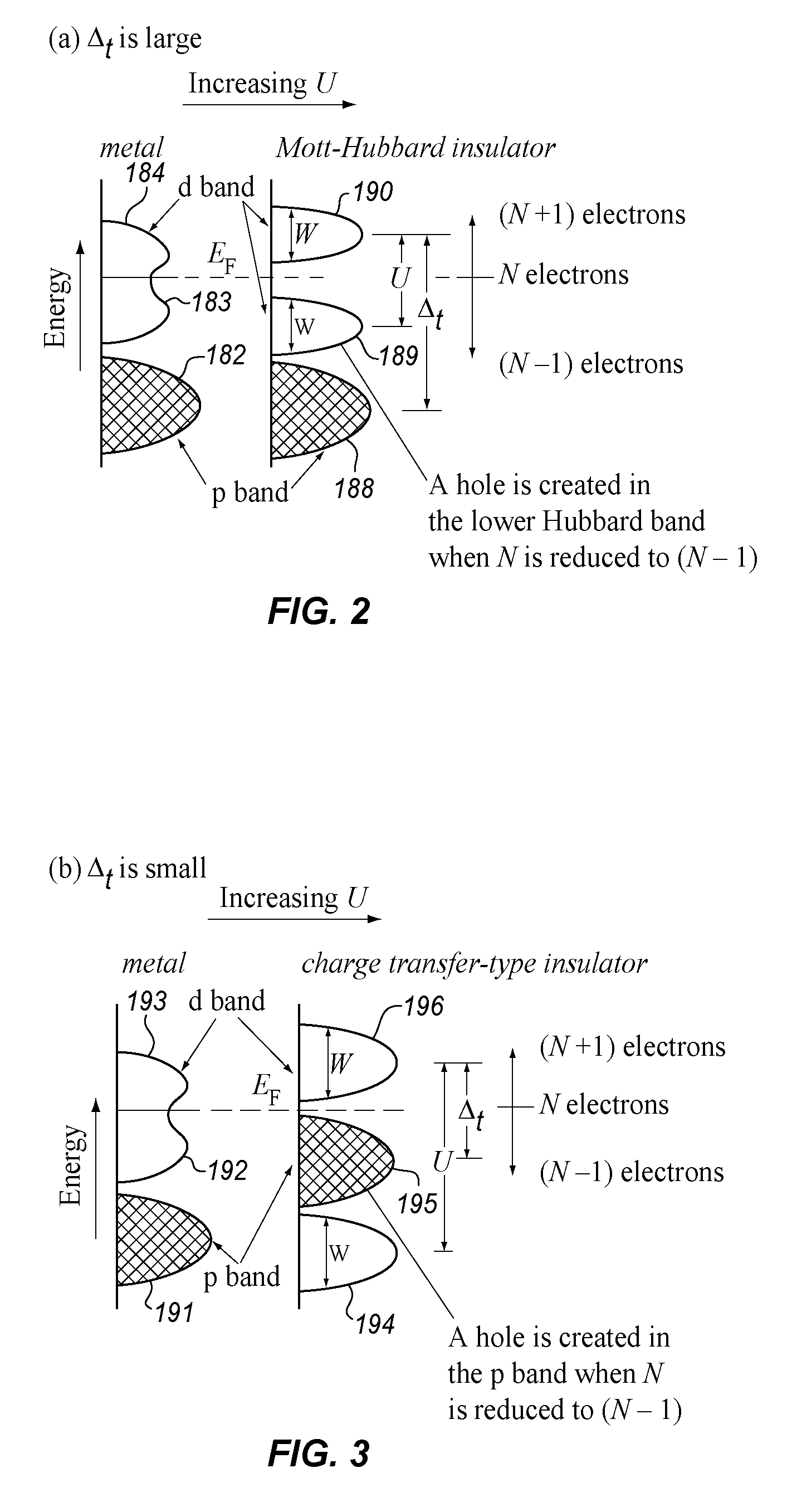
[0038]The present disclosure focuses on transition metal oxide materials, particularly those which exhibit a metal / insulator transition of any type, which we shall refer to herein as variable resistance materials. The transition metal oxides are formed from elements that have a partially filled 3d band and materials with partially filled 3f bands in the periodic table. The most well known of these oxides are vanadium oxide and nickel oxide. The materials with partially filled 3d bands or partially filled 3f bands are sometimes described also as metal / insulator phase transition materials. However, such metallic to insulator transition can also occur in combining transition metals with other materials of systems such as sulfides, iodines, tellurides, and others that do not involve oxygen. In all such materials, which include groups IIIB up to and including group IIB (from column three to twelve across the Periodic Table—for half filled 3d materials and the elements 57 to 71 and 89 to ...
PUM
 Abstract
Description
Claims
Application Information