Method of enhancing performance of cerium doped lutetium yttrium orthosilicate crystals and crystals produced thereby

Active Publication Date: 2007-01-23
CRYSTAL PHOTONICS
View PDF20 Cites 36 Cited by
  • Summary
  • Abstract
  • Description
  • Claims
  • Application Information

AI Technical Summary

Benefits of technology

[0019]In view of the foregoing background, it is therefore an object

Problems solved by technology
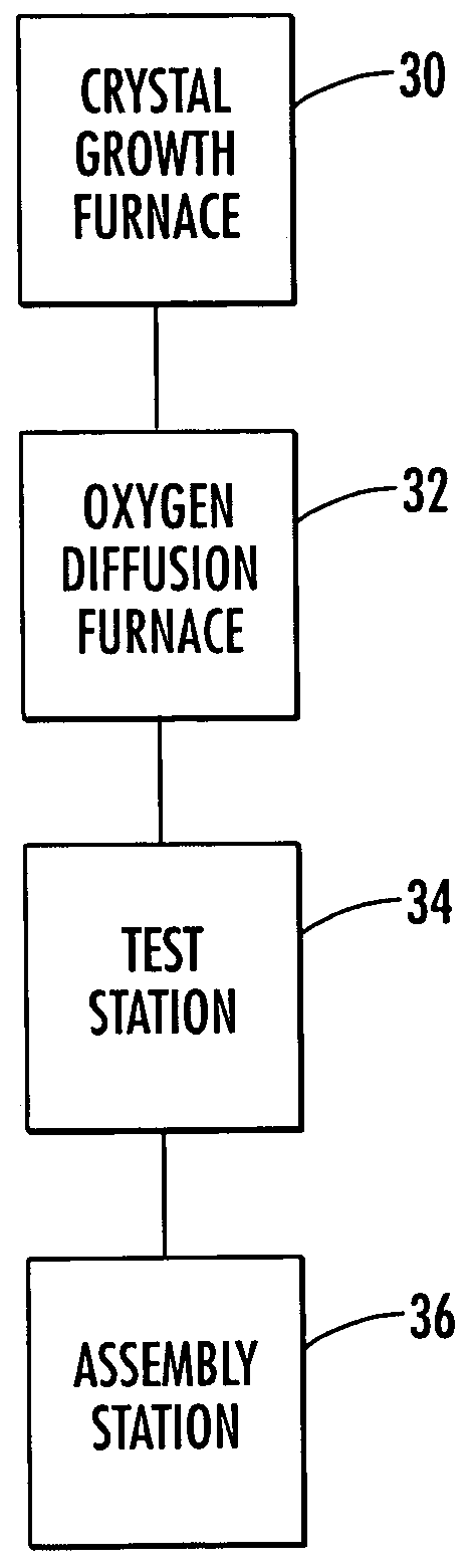
If a sufficient amount of cerium is oxidized the monocrystalline body may ap

Method used


Image

  • Method of enhancing performance of cerium doped lutetium yttrium orthosilicate crystals and crystals produced thereby
  • Method of enhancing performance of cerium doped lutetium yttrium orthosilicate crystals and crystals produced thereby
  • Method of enhancing performance of cerium doped lutetium yttrium orthosilicate crystals and crystals produced thereby

Examples


example 1

[0046]A Ce:LYSO crystal having y=0.05 was cut into pixels of approximately 4×6×30 mm, resulting in ten individual samples which were then placed in an oven heated to 1100° C. for a period of 60 hours. The light yield (LY), the FWHM of the energy peak and energy resolution (ER %) before and after this thermal oxygenation process are listed in Table 1. It should also be understood that all test results shown in Tables 1–9 were measured at standard room temperature of approximately 25° C.

[0047]

TABLE 1Sample #12345678910Initial LY661657666651639603672618668638FWHM11511779102777582828162ER (%)17.417.811.915.712.112.412.213.312.19.760 hrs LY691722715729723705717709727723FWHM61636466615460626162ER (%)8.88.79.09.18.47.78.48.78.48.6

[0048]The results show a general increase of LY following thermal oxygenation. More importantly, the energy resolution improves by at least 10%, after treatment.

example 2

[0049]A Ce:LSO crystal with y=0 is cut into pixels of approximately 6×6×25 mm and the samples were placed in an oven heated to 1100° C. for a period of 60 hours. The results are shown in Table 2. The initial pixel light yield was quite low, about 300, and the energy resolution was also poor. After thermal oxygenation, however, the pixel light yield has generally doubled and shifted to 600. The samples still retained their original light yield peak and the LY became doubled-peaked with an energy resolution more than twice of the original. It was apparent that the same oxygenation treatment is insufficient for LSO, when compared to LYSO. In view of the first results, it was decided to treat the samples for an additional 60 hours at 1100° C. Following this second treatment, there is a clear improvement for both light yield performance and energy resolution. However, the double peak has not been totally eliminated, and three of the samples show two distinctly separated peaks.

[0050]

TABLE...

example 3

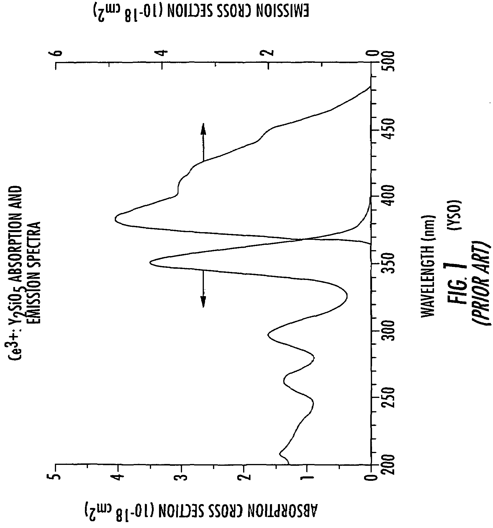
[0052]A Ce:YSO crystal with y=1.00 was cut into a small block of 6×6×10 mm and placed in an oven heated to 1100° C. for a period of 60 hours. The pixel has an initial light yield of 397 and an energy resolution of 10.6%. After the thermal oxygenation process, the crystal color turned to a light yellow, indicating conversion of at least part of the Ce dopant from the 3+ state to the 4+ state. Ce3+ is an efficient blue emitter whereas Ce4+ does not emit at all. Light yield measurement showed that the energy peak was located at 452 channels, which is better than before treatment, and that post-treatment energy resolution is 10.0%. While thermal oxygenation does improve the light yield in this case, the improvement is more limited. It also seems that the oxygen diffusion is more easily obtained in YSO than LYSO, with concomittant oxidation of the cerium dopant. These results indicated a need for shortening the treatment time to prevent oxidation of cerium in the crystal.


PUM


Abstract

A method for enhancing the light yield of a single crystal of cerium doped lutetium yttrium orthosilicate (LYSO) in response to irradiation with high energy radiation includes diffusing oxygen into the crystal by heating the crystal for a period of time in an ambient containing oxygen. This process of thermal oxygenation of the crystal effectively supplies oxygen to fill at least some of the oxygen vacancies in the body of monocrystalline LYSO. A scintillation detector comprises a monocrystalline body of LYSO enhanced by oxygen diffusion into the crystal.

Description

FIELD OF THE INVENTION[0001]The present invention relates to the field of crystals and, more particularly, to a method of enhancing a crystal of cerium doped lutetium yttrium orthosilicate (LYSO) to generate a greater light yield in response to irradiation with high energy radiation.BACKGROUND OF THE INVENTION[0002]Single crystal scintillation is a very simple but also very sensitive method of detecting high energy radiation such as x-rays, gamma-rays and high energy particles with energies exceeding a few kilo-electron volt (KeV). In the past century, a large number of crystals have been proposed for potential scintillating applications. For medical imaging such as positron emission tomographs (PET), crystals with the highest light yield, narrowest energy resolution and fastest decay time are required. Moreover, PET also requires a crystal with good physical integrity and chemical inertness. Thallium-activated sodium iodide, NaI(TI) has by far the highest light yield of 38,000 phot...

Claims


Application Information

Patent Timeline
IPC IPC(8): G01T1/20
CPCC09K11/7774G01T1/2023C30B29/34C30B15/00G21K4/00C30B15/10C09K11/77742
Inventor CHAI, BRUCE
Owner CRYSTAL PHOTONICS
Why Eureka
Try Eureka