Communications system

a communication system and communication technology, applied in the field of communication systems, can solve the problems of variation of the mean intensity at reception, inability to disclose a truly secure communication, and inability to easily interpret signals, and achieve the effect of superior atmospheric propagation

Inactive Publication Date: 2009-12-29
QINETIQ LTD
View PDF6 Cites 2 Cited by
  • Summary
  • Abstract
  • Description
  • Claims
  • Application Information

AI Technical Summary

Benefits of technology

[0014]The invention provides the advantage that its communications signals have an average intensity that is not distinguishable from background; the signals are therefore not immediately apparent as being available for unauthorised receipt, and integrate to a background value in instruments with sufficiently long integrating time.
[0016]In a preferred embodiment, the source of modulated radiation is a light emitting diode of cadmium mercury telluride or of an indium antimonide based material with an operating wavelength band in the range 3 μm to 15 μm. This provides the advantage of superior atmospheric propagation through smoke and mist as compared to communications systems with lower operating wavelengths. The source may be modulated at a modulation rate which is in excess of a typical thermal imager frame rate of 50 Hz, in order to render the source indiscernible from its surrounding environment by means of a thermal imager. The modulation rate may be in excess of 100 Hz.

Problems solved by technology

However GB 776 129 does not disclose a truly secure communication.
The presence of a signal can be detected, albeit that the signal is not readily interpreted.
Breakage or unauthorised tapping along the fibre optic line results in a variation of the mean intensity at reception.
By this means, unauthorised disturbance can be detected.
Again, however, this does not mask the presence of a signal.
This therefore lessens the chance of permanent head magnetisation and consequent performance decline.
Thus conventional secure communication systems suffer from the disadvantage that it is difficult to mask the entire signal.
This may betray the presence of a transmitter and possibly prompt decoding activities by unauthorised detectors.

Method used


Image

  • Communications system
  • Communications system
  • Communications system

Examples


Embodiment Construction

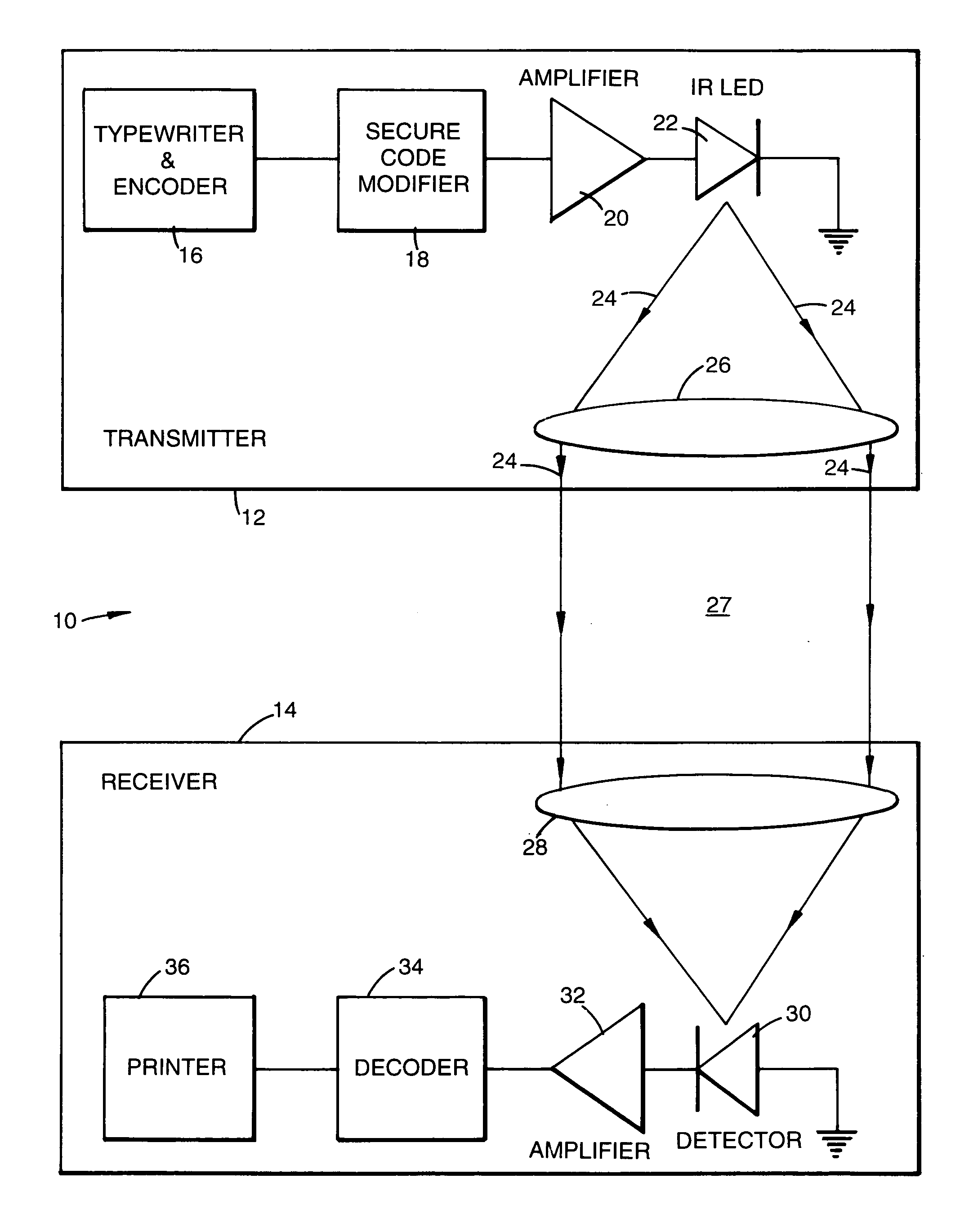
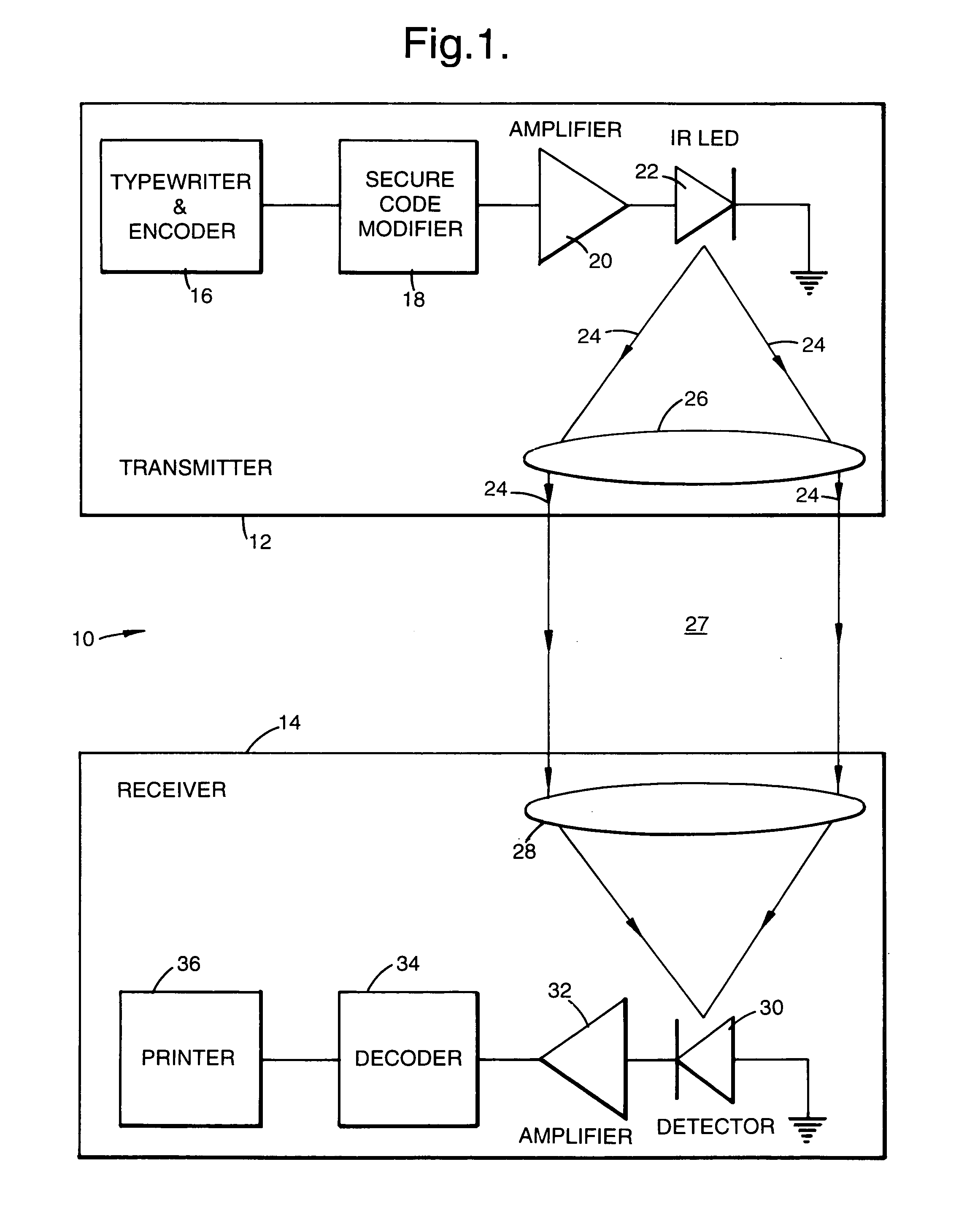
[0031]Referring to FIG. 1, a communications system of the invention indicated generally by 10 is shown schematically. It incorporates a transmitter 12 and a receiver 14.

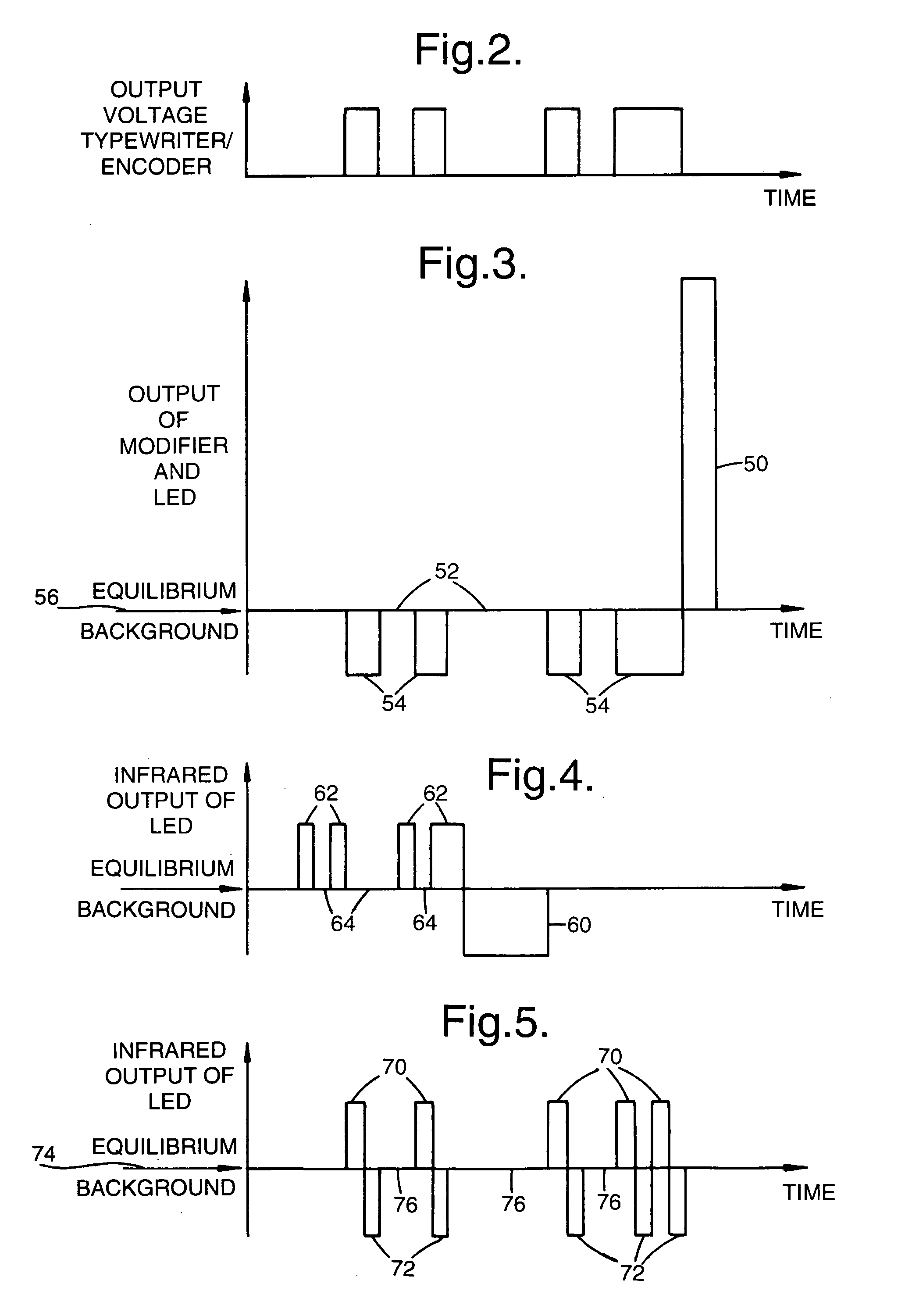
[0032]The transmitter 12 incorporates a typewriter and encoder 16 connected via a secure code modifier 18 to an amplifier 20. The amplifier 20 is connected to an infrared (IR) light emitting diode (LED) 22. The LED 22 is of material appropriate for IR emission, such as for example cadmium mercury telluride or indium antimonide. It has an operating wavelength band in the range 3 μm to 15 μm, which exhibits superior propagation through smoke and mist as compared to shorter wavelengths. The LED 22 is of the kind which provides positive luminescence in response to input bias signals of one polarity and negative luminescence in response to bias signals of the opposite polarity. Negative luminescence is known. It relates to emission of less radiation than a background level, and is described by Bolgov et al, in Semiconduct...


PUM


Abstract

A communications system incorporates a transmitter a receiver. The transmitter includes an infrared light emitting diode (LED). The LED output is positive or negative luminescence, i.e. above or below an equilibrium background intensity level respectively, according to the polarity of its bias signal. The receiver contains a lens to focus light from the LED onto a diode detector, from which signals pass to an amplifier, decoder and printer. Output signals from the LED have an average intensity equal to the equilibrium background intensity level and a frequency greater than 100 Hz or byte rate greater than 100 bytes / sec. They are not discernible by conventional thermal infrared imagers with frame rates of 50 Hz or less because integration in such an imager renders them indistinguishable from background.

Description

BACKGROUND OF THE INVENTION[0001]1. Field of the Invention[0002]This invention relates to a communications system and to a method of communicating.[0003]2. Discussion of Prior Arts[0004]Communications systems are well known in the prior art. Those employing infrared radiation as the carrier signal permit the elimination of special transmitting media such as wires without being subject to the broadcasting regulations of radio frequency transmission systems. The first capability offers significant advantages in applications for which space, presentation or frequent reconfiguration are essential requirements. The second makes infrared communication an attractive alternative to radio communication. Generally infrared communication systems can be loosely divided into those in which unauthorised interception of information is unimportant (e.g. those based on an extension of a television remote control principle) and those in which it could have serious consequences (e.g. secure communicat...

Claims


Application Information

Patent Timeline
Patent Type & Authority Patents(United States)
IPC IPC(8): H04B10/00H04B10/112
CPCH04B10/1121
Inventor ASHLEY, TIMOTHYCARMICHAEL, IAN CHARLESELLIOT, CHARLES THOMASGLEAVES, DAVID GEORGEGORDON, NEIL THOMSONHALL, RALPH STEPHENSON
Owner QINETIQ LTD
Why Eureka
Try Eureka