Apparatus and method for forming corrugated members

a technology of corrugated members and apparatuses, which is applied in the direction of manufacturing tools, forging/pressing/hammering apparatuses, forging/hammering/pressing machines, etc., can solve the problems of inability to accurately determine the spring back, add to the cost and complexity of manufacturing processes, and the web cannot be lined up and welded with the flange in the desired configuration. to achieve the effect of reducing the cost and complexity of operation

Active Publication Date: 2010-01-05
THE BOEING CO
View PDF41 Cites 5 Cited by
  • Summary
  • Abstract
  • Description
  • Claims
  • Application Information

AI Technical Summary

Benefits of technology

[0011]The apparatus can also include a welding tool that is configured to weld each flange to the web while the web is supported between the forming surfaces of the dies and the contour surface of the strongback. For example, the welding tool can be a laser welder that is configured to provide a laser beam on each flange at a position opposite the web and thereby weld the flange to the web. In some cases, the laser welding can be performed without the use of a filler material, thereby reducing the cost and complexity of the operation. A controller can be configured to adjust the power and / or speed of motion of the welding tool to thereby control the operation of the welding tool according to at least one of a location of the welding tool along the support structure and a physical parameter of the stringer along the length thereof.
[0012]According to one embodiment, the apparatus includes a gas chamber that is configured to be adjusted along a length of the strongback with the welding tool. The gas chamber defines an opening directed toward one of the flanges and the web supported by the strongback and dies. A gas source is configured to deliver a gas, typically an inert gas, to the gas chamber during operation of the welding tool so that the chamber is maintained substantially full of the gas and each flange is welded to the web in a local environment of the gas. Further, the strongback and dies can define channels along the longitudinal direction of the apparatus, and a gas source can be configured to deliver a gas into the channels. The provision of an inert gas to local regions of the flanges and webs where weld joints are to be formed can avoid the necessity and associated expense of a large vacuum chamber for receiving the entire flanges and webs during welding.
[0016]In some cases, the apparatus and method can be used without pre-forming (or without substantial pre-forming) of the web and flanges. That is, the web and flanges can be provided in conventional stock shapes and configurations. Further, the forming operations of the present invention can be performed without significant pre-heating of the web and flanges. Thus, the costs, time, and tooling associated with pre-forming and pre-heating can be reduced or eliminated, and the apparatus and method of the present invention can provide for variable wave geometry in the finished member, thereby increasing the shaping flexibility or versatility of the apparatus and method.

Problems solved by technology

However, an accurate determination of spring back can be difficult or impossible and can add to the cost and complexity of the manufacturing process.
Thus, in some cases, the web may not be lined up and welded with the flanges in the desired configuration, and the desired configuration of the stringer may not be achieved.
The manufacturing operation of such corrugated stringers can be further complicated by the use of materials with special forming or processing requirements and characteristics.
This evacuation method increases the time and expense for welding.

Method used


Image

  • Apparatus and method for forming corrugated members
  • Apparatus and method for forming corrugated members
  • Apparatus and method for forming corrugated members

Examples


Embodiment Construction

[0034]The present inventions now will be described more fully hereinafter with reference to the accompanying drawings, in which some, but not all embodiments of the inventions are shown. Indeed, these inventions may be embodied in many different forms and should not be construed as limited to the embodiments set forth herein; rather, these embodiments are provided so that this disclosure will satisfy applicable legal requirements. Like numbers refer to like elements throughout.

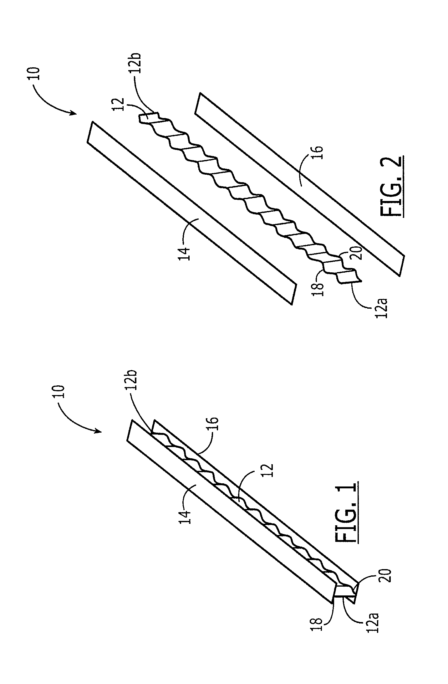
[0035]Referring now to FIG. 1, there is illustrated a corrugated stringer 10 formed according to one embodiment of the present invention. For purposes of illustrative clarity, the corrugated stringer 10 is shown in an unassembled configuration in FIG. 2. As illustrated, the corrugated stringer 10 includes a web 12 that defines a desired corrugated configuration. The web 12 extends between first and second flanges 14, 16 that are welded thereto. That is, as shown in FIG. 1, the first flange 14 is welded to a fi...


PUM

PropertyMeasurementUnit
temperaturesaaaaaaaaaa
radius of curvatureaaaaaaaaaa
speedaaaaaaaaaa

Abstract

An apparatus and method for forming a stringer are provided. The stringer generally includes a web having a desired corrugated configuration and first and second flanges welded to opposite edges of the web. The apparatus includes a support structure, a strongback that is supported by the support structure, and a plurality of dies that are adjustable relative to the strongback. The strongback defines a corrugated contour surface corresponding to the desired corrugated configuration of the web. The dies define corresponding forming surfaces and are configured to be advanced toward the strongback to thereby form the web to the desired corrugated configuration between the contour surface of the strongback and the forming surfaces of the dies. Further, the apparatus can receive the flanges of the stringer in a predetermined configuration with the web so that the flanges can be welded to the web while the web is supported by the strongback and dies in the desired corrugated configuration.

Description

BACKGROUND OF THE INVENTION[0001]1) Field of the Invention[0002]The present invention relates to the forming of members and, more particularly, an apparatus and method for forming corrugated contours in a member, such as a metal web that is disposed between flanges to produce a stringer or beam.[0003]2) Description of Related Art[0004]Corrugated members are widely used for a variety of applications. For example, metal structural panels used in vehicles, buildings, and containers can be corrugated to provide an increased resistance to bending or buckling relative to flat sheets. A corrugated web can be used to form a structural component such as a beam or stringer. For example, a corrugated stringer, which includes a corrugated web that extends between top and bottom flanges, can be used in the construction of a larger assembly such as an aircraft wing or fuselage. The profile of such a corrugated member typically defines wave-like sinusoidal contours, which affect the rigidity and o...

Claims


Application Information

Patent Timeline
Patent Type & Authority Patents(United States)
IPC IPC(8): B23K26/20B21D47/01
CPCB21D13/02Y10T29/49634
Inventor KISMARTON, MAX U.GREGG, PAUL S.WILL, JEFF D.
Owner THE BOEING CO
Why Eureka
Try Eureka