Slot type antenna with integrated amplifiers

a slot antenna and amplifier technology, applied in the direction of slot antennas, antenna details, antennas, etc., can solve the problems of additional losses, certain limitations in frequency bandwidth related to the bandwidth of hybrid rings, etc., and achieve the effect of simplifying the representation

Inactive Publication Date: 2010-01-05
THOMSON LICENSING SA
View PDF4 Cites 8 Cited by
  • Summary
  • Abstract
  • Description
  • Claims
  • Application Information

AI Technical Summary

Problems solved by technology

This configuration also causes additional losses provided by the hybrid rings and certain limitations in frequency bandwidth related to the bandwidths of the hybrid rings.

Method used


Image

  • Slot type antenna with integrated amplifiers
  • Slot type antenna with integrated amplifiers
  • Slot type antenna with integrated amplifiers

Examples


Embodiment Construction

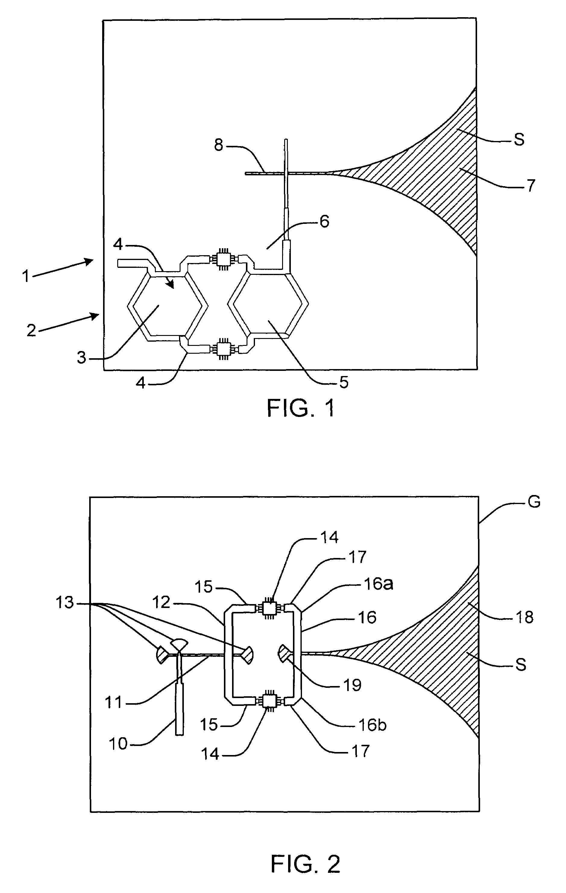
[0025]A first embodiment of the present invention will now be described with reference to FIGS. 2 to 4.

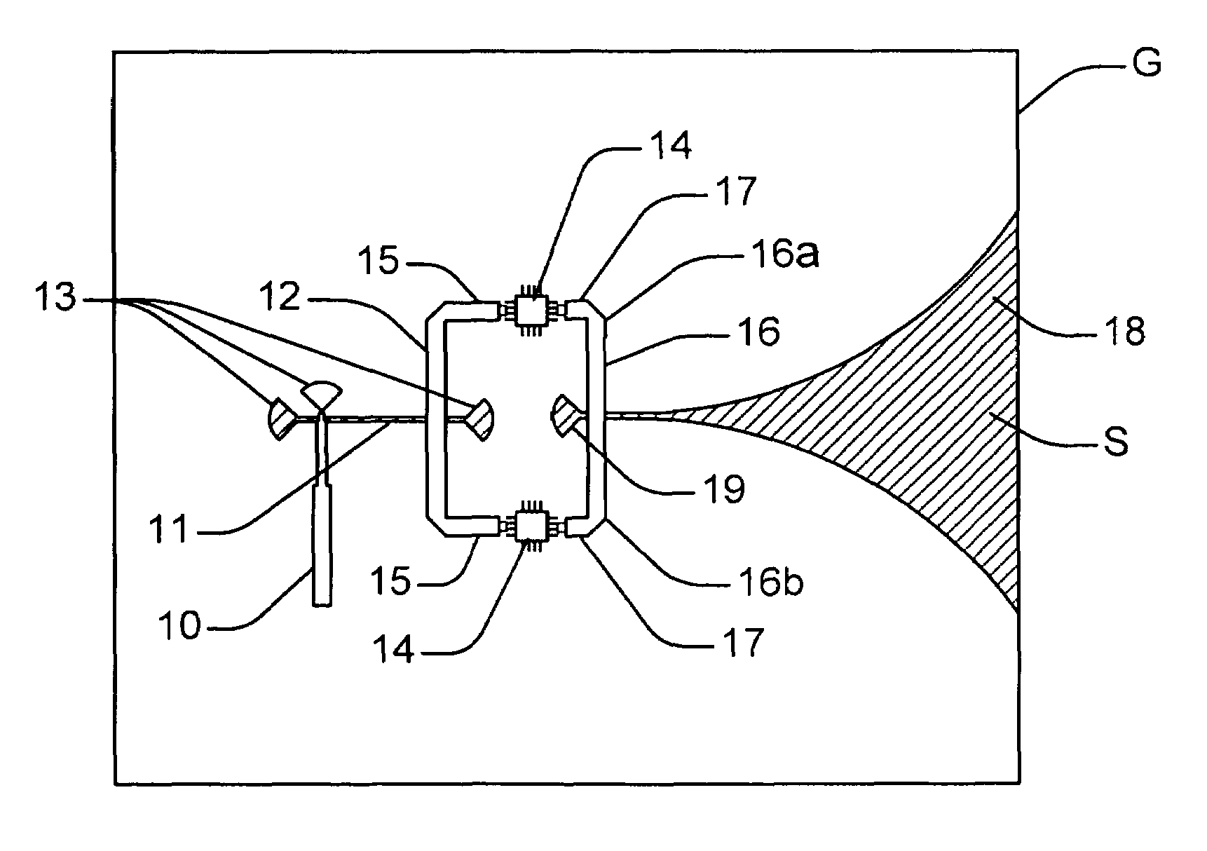
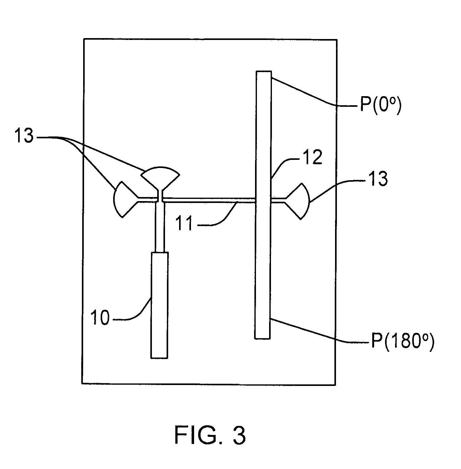
[0026]Hence, as illustrated in FIG. 2, on a substrate S featuring a ground plane G, a longitudinal radiation slot type antenna was realized, more particularly in this case a Vivaldi type antenna 18. Furthermore, on the same substrate, we have integrated the power amplification circuit. In greater detail and as illustrated in FIG. 2, the power amplification circuit comprises a feeder line 10 realized using microstrip technology. This feeder line 10 is coupled electromagnetically according to a coupling of the Knorr type with a first slot line 11. The slot line 11 is coupled at the output with a first microstrip line 12. The coupling of the microstrip line 12 with the slot line 11 is realized in the middle of the microstrip line by using an electromagnetic coupling of the Knorr type. Moreover, to realize the impedance matching of the assembly, “stubs”13 are provided at each extremity...


PUM


Abstract

The present invention relates to a slot type antenna with integrated amplifiers, comprising a substrate S featuring a ground plane G, a longitudinal radiation open slot antenna, a power divider connected to a feeder line, an amplifier connected to each of the outputs of the power divider, such that the amplifiers are supplied in phase opposition, the output of the amplifiers being connected to a power combination circuit directly coupled to the excitation point of the slot type antenna.

Description

[0001]This application claims the benefit, under 35 U.S.C. §119 of French Patent Application 0653205, filed Jul. 31, 2006.[0002]The invention relates to antennas with integrated amplifiers, more particularly an open slot antenna such as a Vivaldi antenna or an antenna of a similar type connected to power amplifiers integrated on the same substrate.BACKGROUND OF THE INVENTION[0003]Wi-Fi technology operating in accordance with the IEEE802 11a / b / g standard and operating in the 2.4 GHz and 5 GHz frequency bands today holds the best position for very high speed wireless transmissions, especially in a domestic environment.[0004]The transmission of several video streams, particularly high definition between for example, a station or set top box (STB) and several terminals such as computer laptops, television or other devices, requires the use of a high-order modulation to attain the maximum speed allowed by the standard, namely 54 Mbps. The high-order modulations such as the 64-QAM modulat...

Claims


Application Information

Patent Timeline
Patent Type & Authority Patents(United States)
IPC IPC(8): H01Q13/10
CPCH01Q9/045H03F3/60H01Q23/00H01Q13/085H01Q13/08
Inventor LOUZIR, ALILO HINE TONG, DOMINIQUEMINARD, PHILIPPEMARNAT, LOIC
Owner THOMSON LICENSING SA
Why Eureka
Try Eureka