Optical scanning apparatus and image forming apparatus

a scanning apparatus and optical scanning technology, applied in the field of optical scanning apparatus and image forming apparatus, can solve the problems of rotary polygon mirror, increase in power consumption, slow scanning speed near the peripheral image height,

Inactive Publication Date: 2010-01-05
RICOH KK
View PDF12 Cites 9 Cited by
  • Summary
  • Abstract
  • Description
  • Claims
  • Application Information

AI Technical Summary

Problems solved by technology

The rotary polygon mirror, however, is large, and its high-speed mechanical rotation generates vibrations which induce various inconveniences such as banding, temperature rise, noises, and increase in power consumption.
However, when the micro mirror is employed as the deflector together with the f-theta lens in a scanning / imaging optical system, scanning speed slows near a peripheral image height and is not constant over the scanned surface.
In the disclosed optical scanning apparatus, however, when the optical correction is performed as described above, a spot diameter of the main scanning light beam on the scanned surface deviates more widely corresponding to the image height, thereby degrading the image quality.
However, every embodiment disclosed in Japanese Patent Application Laid-Open No. 2005-215571 has problems as described below and has not succeeded in solving the problems mentioned above.
Thus, high-quality images cannot be obtained.
However, since the swing angle of the micro mirror is small, an effective writing width for image formation cannot be secured without a long distance between the micro mirror and the scanned surface.
This requirement makes the optical scanning apparatus larger, limiting the overall dimension of the apparatus.
Thus, there is a limitation on the overall dimension of the apparatus.
However, the linearity on the scanned surface is significantly biased toward the negative side, and the constancy of the scanning speed is deteriorated.

Method used


Image

  • Optical scanning apparatus and image forming apparatus
  • Optical scanning apparatus and image forming apparatus
  • Optical scanning apparatus and image forming apparatus

Examples


first embodiment

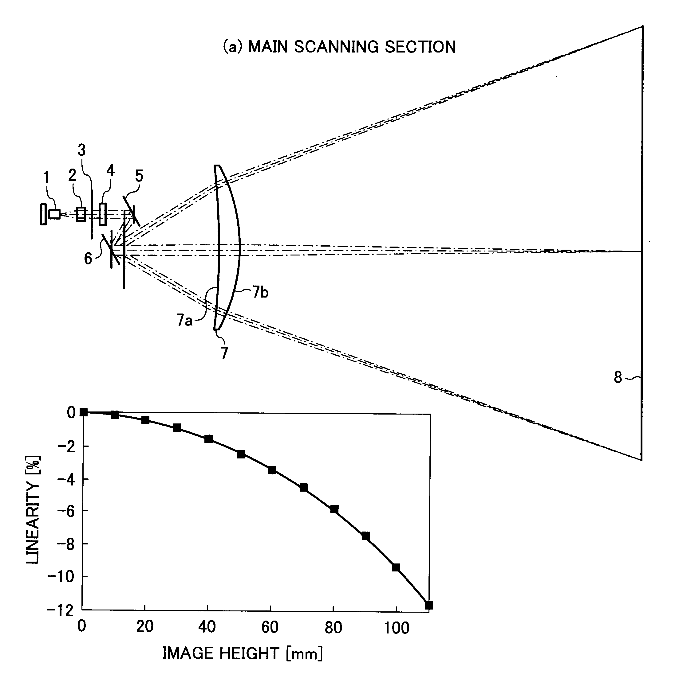
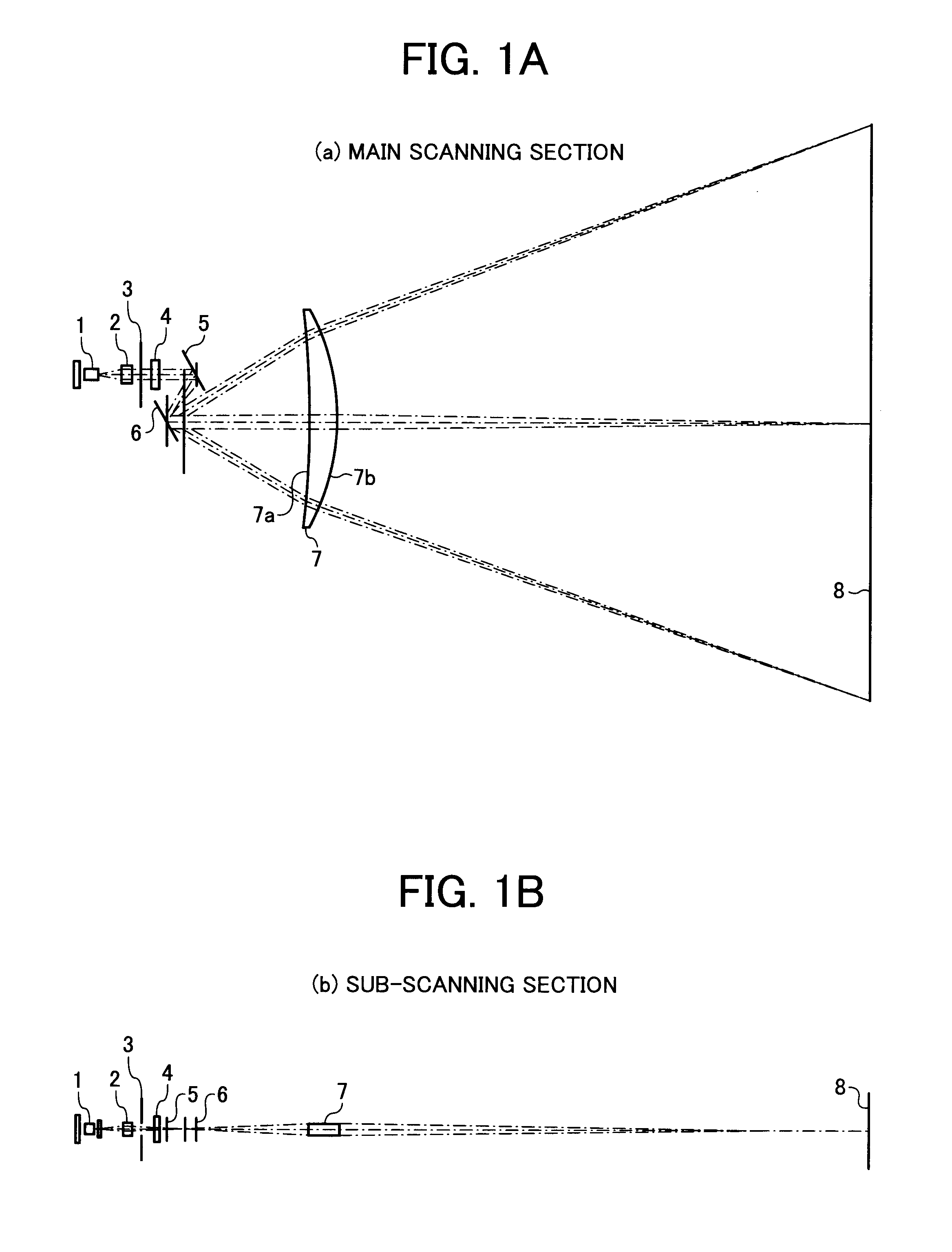
[0041]Design data of an optical scanning apparatus according to a first embodiment of the present invention will be described below. Since the optical scanning apparatus according to the first embodiment is not largely different from the optical scanning apparatus having the structure shown in FIG. 1, the first embodiment will be described with reference to FIG. 1. Vibration characteristics of a sinusoidal vibration mirror which serves as the deflector 6 can be represented as follows:

φ0:±25°,

φmax+15°,

and hence, φmax / φ0=0.600.

[0042]Here, the light beam is collected along the sub-scanning direction and comes into the sinusoidal vibration mirror as the deflector 6 at one point on the sinusoidal vibration mirror as the deflector 6.

[0043]A lens surface of the scanning / imaging lens 7 at the side from which the light beam enters is denoted as 7a, and another lens surface of the scanning / imaging lens 7 from which the light beam is emitted is denoted as 7b. Distance between the sinusoidal vi...

second embodiment

With Regard to Lower Limit in Conditional Equation (2)

[0060]Since a structure of an optical scanning apparatus according to a second embodiment is not largely different from the structure of the optical scanning apparatus according to the first embodiment, the optical scanning apparatus according to the second embodiment will be described with reference to FIG. 1 again. The optical scanning apparatus according to the second embodiment is different from the optical scanning apparatus according to the first embodiment in that the amplitude angle φ0 of the sinusoidal vibration mirror serving as the deflector 6 is set as:

φ0:±24°.

[0061]The maximum rotational angle φmax of the sinusoidal vibration mirror corresponding to the effective writing width in the second embodiment is, similarly to the first embodiment:

φmax:±15°,

and therefore,

φmax / φ0=0.625.

In comparison with the first embodiment, the rate of the maximum rotational angle corresponding to the effective writing width to the amplitude...

third embodiment

With Regard to Upper Limit in Conditional Equation (4)

[0066]Since a structure of an optical scanning apparatus according to a third embodiment is not significantly different from the structure of the optical scanning apparatus according to the first embodiment, the third embodiment will be described with reference to FIG. 1 again. Here, the optical scanning apparatus of the third embodiment is different from the optical scanning apparatus of the first embodiment in that the amplitude angle φ0 of the sinusoidal vibration mirror which serves as the deflector 6 is set as:

φ0:±28°.

[0067]Further, the maximum rotational angle φmax of the sinusoidal vibration mirror corresponding to the effective writing width in the third embodiment is set similarly to the first embodiment as:

φmax:±15

and therefore,

φmax / φ0=0.536

Since the rate of the maximum rotational angle corresponding to the effective writing width to the amplitude angle of the sinusoidal vibration mirror is decreased in comparison with ...


PUM


Abstract

An optical scanning apparatus includes a light source, a light source driving unit that turns on the light source according to image information, a deflector that deflects and scans a light beam emitted from the light source according to sinusoidal vibration, and a scanning / imaging optical system that guides the light beam from the deflector to a scanned surface. The scanning / imaging optical system satisfies two conditions, i.e., (1) provided that the deflector moves in such a manner that an angular velocity is constant, linearity is made larger at a most peripheral image height than at a central image height within a range of an effective writing width, and (2) when a deflection angle of the deflector has a sinusoidal characteristic, the linearity is made smaller at the most peripheral image height than at the central image height within the range of the effective writing width.

Description

CROSS-REFERENCE TO RELATED APPLICATIONS[0001]The present document incorporates by reference the entire contents of Japanese priority document, 2006-171546 filed in Japan on Jun. 21, 2006.BACKGROUND OF THE INVENTION[0002]1. Field of the Invention[0003]The present invention relates generally to an optical scanning apparatus and an image forming apparatus. More particularly, the present invention relates to a deflection mirror (vibration mirror) which is applicable to, for example, optical scanning apparatuses, light-scanning type display devices, and in-vehicle laser radar apparatuses, an optical scanning apparatus which includes such a deflection mirror, and an image forming apparatus, such as a digital copier, a printer, a plotter, and a facsimile that includes the above optical scanning apparatus.[0004]2. Description of the Related Art[0005]Conventionally known optical scanning apparatus deflects a light beam using a deflector such as a light deflecting unit, focuses the deflected ...

Claims


Application Information

Patent Timeline
Patent Type & Authority Patents(United States)
IPC IPC(8): G02B26/08
CPCG02B26/105G02B26/123
Inventor NAKAMURA, TADASHIHAYASHI, YOSHINORIMIYATAKE, NAOKI
Owner RICOH KK
Why Eureka
Try Eureka