Ribbon wound roll

a ribbon and wounding technology, applied in the direction of manufacturing tools, portable power tools, transportation, etc., can solve the problems of increasing costs, destroying the entire mold, and achieving the effect of improving the uniformity of products, improving thermal control of mold cavities, and small thermal mass of ribbons

Inactive Publication Date: 2010-01-12
3M INNOVATIVE PROPERTIES CO
View PDF27 Cites 7 Cited by
  • Summary
  • Abstract
  • Description
  • Claims
  • Application Information

AI Technical Summary

Benefits of technology

[0013]Yet another advantage of the present invention is the relatively small thermal mass of the ribbon or ribbons wrapped around the cylindrical base in comparison to the thermal mass of the cylindrical base, particularly a cylindrical base roll. As a result, thermal control over the mold cavities can be improved, which can result in corresponding improvements in the uniformity of the products produced using the tool rolls.
[0014]As used in connection with the present invention, a “mold cavity” may be any discontinuity in an otherwise smooth or planar surface into which moldable material may flow during a molding process. In some embodiments of the present invention, the tool rolls may include mold cavities with high aspect ratios as defined below, although it should be understood that a mold cavity need not have a high aspect ratio.
[0015]In one aspect, the present invention provides a tool roll with a cylindrical base and a first ribbon having an inner face, an outer face, and first and second major sides located therebetween. The outer face of the first ribbon includes a plurality of depressions or holes formed therein and the first ribbon is wound in helical coils around the base roll such that the inner face is proximate the base roll. The plurality of depressions or holes in the outer face of the first ribbon form a plurality of discrete mold cavities with each of the discrete mold cavities including a mold opening at the outer face of the first ribbon.
[0016]In another aspect, the present invention provides a tool roll including a cylindrical base and a first ribbon with an inner face, an outer face, and first and second major sides located therebetween. The outer face of the first ribbon includes a plurality of depressions or holes formed therein and the first ribbon is wound in helical coils around the cylindrical base such that the inner face is proximate the cylindrical base. The plurality of depressions or holes in the outer face of the first ribbon form a plurality of discrete mold cavities with each of the mold cavities including a mold opening at the outer face of the first ribbon. The tool roll also includes a second ribbon or wire with an inner face, outer face, and first and second major sides located therebetween. The second ribbon or wire is wound in helical coils around the cylindrical base such that the inner face of the second ribbon or wire is proximate the cylindrical base, wherein the second ribbon or wire is located between adjacent helical coils of the first ribbon. The sides and / or inner face of the second ribbon can include a bleed structure formed therein and a face zone free of the bleed structure.
[0017]In another aspect, the present invention provides a tool roll including a cylindrical base and a first ribbon with an inner face, outer face, and first and second major sides located therebetween. The ribbon is wound in helical coils around the base such that the inner face is proximate the base. The first ribbon also includes a plurality of through-holes formed through the outer face to the inner face of the ribbon, wherein each of the holes can include one or more depression extending therefrom. The plurality of holes with depressions extending therefrom form a plurality of composite mold cavities with each of the composite mold cavities having a mold opening at the outer face of the ribbon.
[0018]In another aspect, the present invention provides a tool roll including a cylindrical base and a first ribbon with an inner face, outer face, and first and second major sides located therebetween. The ribbon is wound in helical coils around the base roll such that the inner face is proximate the base. The first ribbon also includes a plurality of depressions formed in the outer face of the first ribbon and a plurality of holes formed through the outer face to the inner face of the ribbon, wherein each of the holes can include one or more depression or secondary holes extending therefrom. The plurality of depressions and holes with depressions extending therefrom form a plurality of composite mold cavities with each of the composite mold cavities having a mold opening at the outer face of the ribbon.

Problems solved by technology

As a result, the cavities are cylindrical in shape and, although some precision can be obtained in depth, diameter and spacing between cavities, it is obtained with some difficulty and increased costs.
Furthermore, damage to the mold surface typically requires that the entire mold be discarded.
Furthermore, precise control over the depth of the cavities is difficult to obtain due to variability in the material used to construct the mold, the power of the laser beam, the energy distribution within the beam, beam focus, etc.
Disadvantages of these designs include the cost of manufacturing the mold disks with adequate precision to ensure that the mold cavities are of the same depth, length, spacing, etc.
Size limitations imposed on the disks by manufacturing difficulties can, in turn, limit line speed in processes using the tools.
Other disadvantages of this design include non-uniform cooling of the mold cavities, non-uniformities in the products produced by the stacked plates, etc.

Method used


Image

  • Ribbon wound roll
  • Ribbon wound roll
  • Ribbon wound roll

Examples


Embodiment Construction

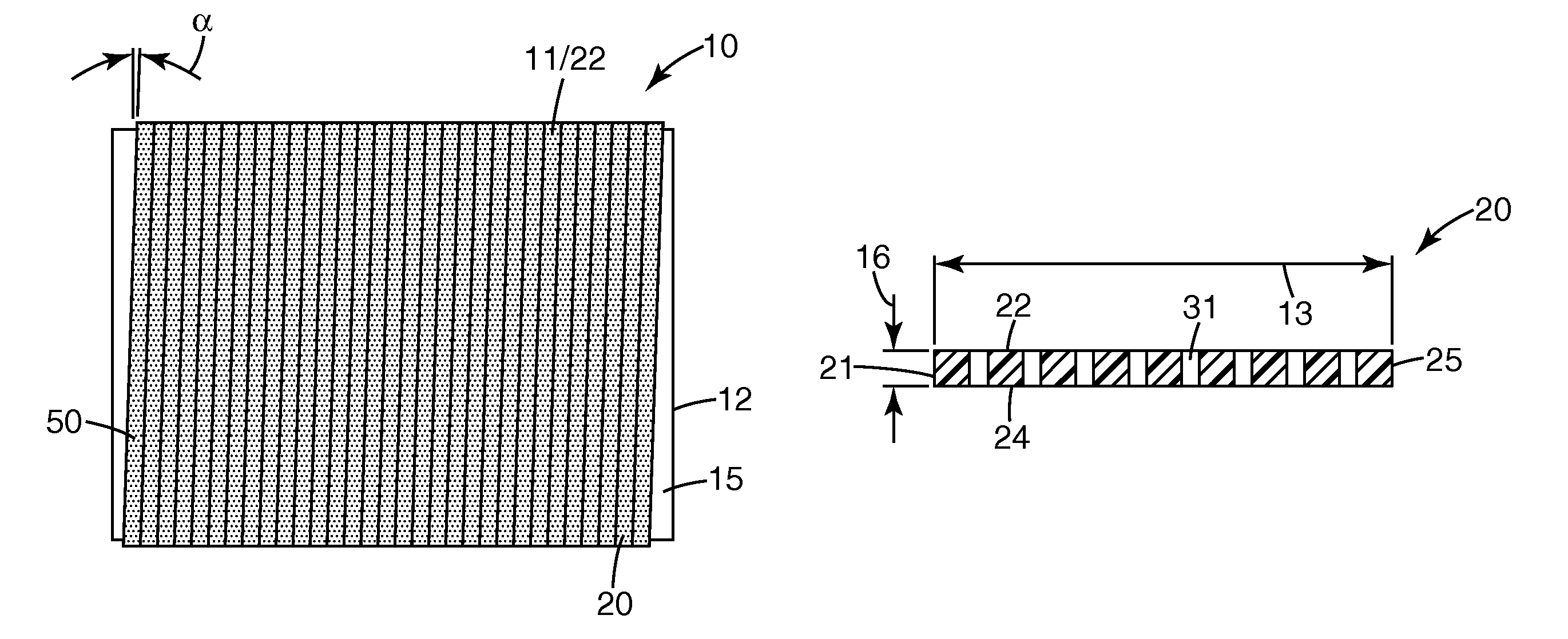
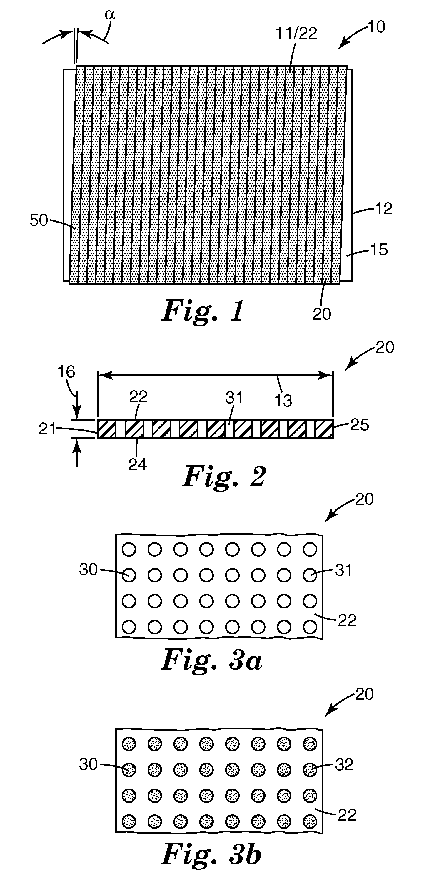
[0034]The present invention provides tool rolls and methods of using the tool rolls to manufacture articles with one or more structured surfaces. The tool rolls include an outer surface that, when used in connection with materials of the proper viscosity or formability, can form a structured surface on an article. Because the tools are manufactured in roll-form, they can be advantageously used in continuous manufacturing processes to form e.g., films, sheets, etc. Alternatively, discrete articles may be processed using the tool rolls of the present invention, which could be used as embossing rolls or the like.

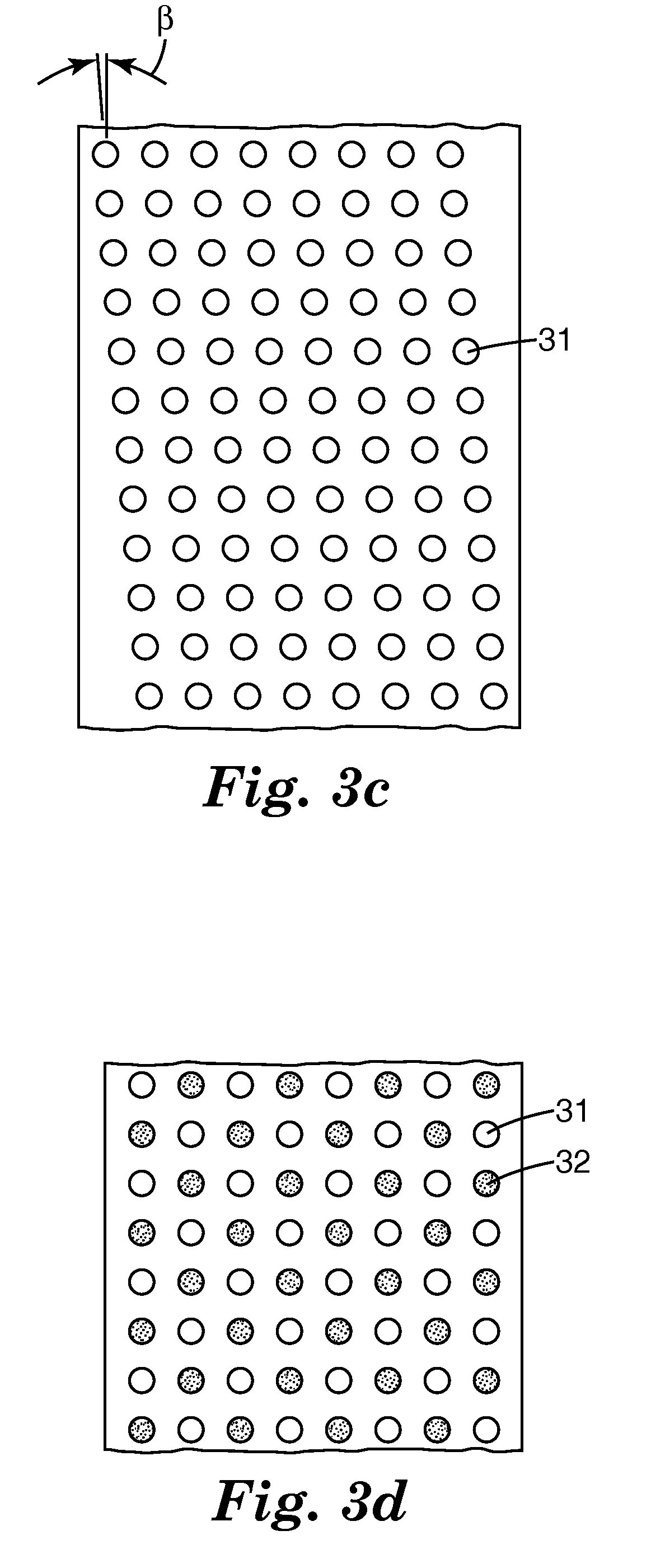
[0035]The tool rolls of the present invention may include mold cavities in their outer surfaces that, when used in connection with materials of the proper viscosity or formability, can form protrusions or structures on at least one surface of a film. The protrusions or structures could be discrete or interconnected. Alternatively, two such rolls can be used in combination to fo...


PUM

PropertyMeasurementUnit
widthaaaaaaaaaa
widthaaaaaaaaaa
thicknessaaaaaaaaaa

Abstract

There is provided a tool roll with a cylindrical base and a first ribbon having an inner face, an outer face, and first and second major sides located therebetween. The outer face of the first ribbon includes a plurality of depressions or holes formed therein and the first ribbon is wound in helical coils around the base roll such that the inner face is proximate the base roll. The plurality of depressions or holes in the outer face of the first ribbon form a plurality of discrete mold cavities with each of the discrete mold cavities including a mold opening at the outer face of the first ribbon.

Description

FIELD OF THE INVENTION[0001]The present invention relates to the field of manufacturing articles with structured surfaces. More particularly, the present invention provides tooling for manufacturing articles with one or more structured surfaces, methods of manufacturing the tooling, and methods of using the tooling to manufacture articles with one or more structured surfaces.BACKGROUND OF THE INVENTION[0002]Articles with one or more structured surfaces find a variety of uses. The articles may be provided as films that exhibit, e.g., increased surface area, structures used to provide a mechanical fastener, optical properties, etc. When these films are manufactured for use as mechanical fasteners, the protrusions that are found on the structured surface are commonly referred to as hooks. The hooks may be formed directly as hooks such as in a curved shape or they may be formed as hook precursors such as substantially upright stems that are deformed at the top such as into the shape of ...

Claims


Application Information

Patent Timeline
Patent Type & Authority Patents(United States)
IPC IPC(8): B29C43/46B29C48/08
CPCB29C33/424B29C43/46B29C59/04B29C47/0021B29C43/222A44B18/0049B29C47/8845B29L2031/729B29C2043/461B29C2043/465B29C48/08B29C48/914B65H75/00B65H75/08
Inventor JACKSON, BYRON M.AUSEN, RONALD W.BEHRENS, MARK S.PARISEAU, TIMOTHY P.
Owner 3M INNOVATIVE PROPERTIES CO
Why Eureka
Try Eureka