
Recording/reproduction apparatus which adjusts recording power based on a partial response maximum likelihood (PRML) technique

a technology of partial response and maximum likelihood, which is applied in the field of recording/reproduction apparatus, recording/reproduction method, program and recording power adjustment apparatus, can solve the problems of difficult evaluation and optimization of the characteristics of the transmission path of reproduction transmission, inability to obtain optimum power, and inability to correctly obtain optimum power, so as to achieve optimized recording state, low error rate during reproduction, and high precision

Active Publication Date: 2010-01-12
PANASONIC CORP
View PDF12 Cites 2 Cited by
  • Summary
  • Abstract
  • Description
  • Claims
  • Application Information

AI Technical Summary

Benefits of technology

"The present invention provides a recording / reproduction apparatus for recording and reproducing information on a medium using different recording powers. The apparatus includes a first recording section for recording test information, a reproduction section for reproducing the test signals, and a second recording section for recording information onto the medium. The reproduction section performs maximum likelihood decoding of the test signals and calculates the reliability of the decoding based on the test signals. The apparatus can adjust the recording power based on the reliability to ensure the recorded information is accurate. The technical effect of the invention is to provide a reliable and accurate recording / reproduction apparatus for recording and reproducing information on a medium."

Problems solved by technology

However, it has been difficult to evaluate and optimize the characteristics of a reproduction transmission path based on the PRML technique.
However, in a method and apparatus which determines an optimum recording power using asymmetry as an index, the optimum power may not be obtained due to insufficient precision in detection of asymmetry.
In a method and apparatus which determines an optimum recording power with the PRML technique using jitter as an index, the optimum power may not be correctly obtained, since a recording power minimizing jitter is not necessarily equal to a recording power minimizing BER.
In a method and apparatus which determines an optimum recording power with the PRML technique using BER as an index, the optimum power may not be obtained due to insufficient precision in detection of the index.
The insufficient precision of detection of the indexes is attributed to the requirement of a large quantity of recording area for measurement of BER, the degradation of BER due to stain, dust or the like on a disc rather than a recorded state, a change in BER (sensitivity) to a recording power due to the high error correction capability of the PRML technique, or the like.
As described above, when a conventional method of setting a parameter for a recording power in a manner which optimizes jitter, asymmetry or BER (e.g., Japan Patent No. 3259642) is applied to a system which employs the PRML technique, the probability of occurrence of error is not necessarily minimized.
In addition, a recording power is not necessarily determined with good precision due to insufficient precision of detection of an index for determining a recording power.
Therefore, a degradation in performance occurs due to cross power (overwrite is performed on a recorded area of a disc under different conditions), which is generated due to error in setting a recording power.
Therefore, it may be difficult to obtain the stable compatibility of optical disc drive apparatuses and optical disc media to the same standard.

Method used


Image

  • Recording/reproduction apparatus which adjusts recording power based on a partial response maximum likelihood (PRML) technique
  • Recording/reproduction apparatus which adjusts recording power based on a partial response maximum likelihood (PRML) technique
  • Recording/reproduction apparatus which adjusts recording power based on a partial response maximum likelihood (PRML) technique

Examples


embodiment 1

2. Embodiment 1

[0090]2-1. Recording / Reproduction Apparatus of Embodiment 1

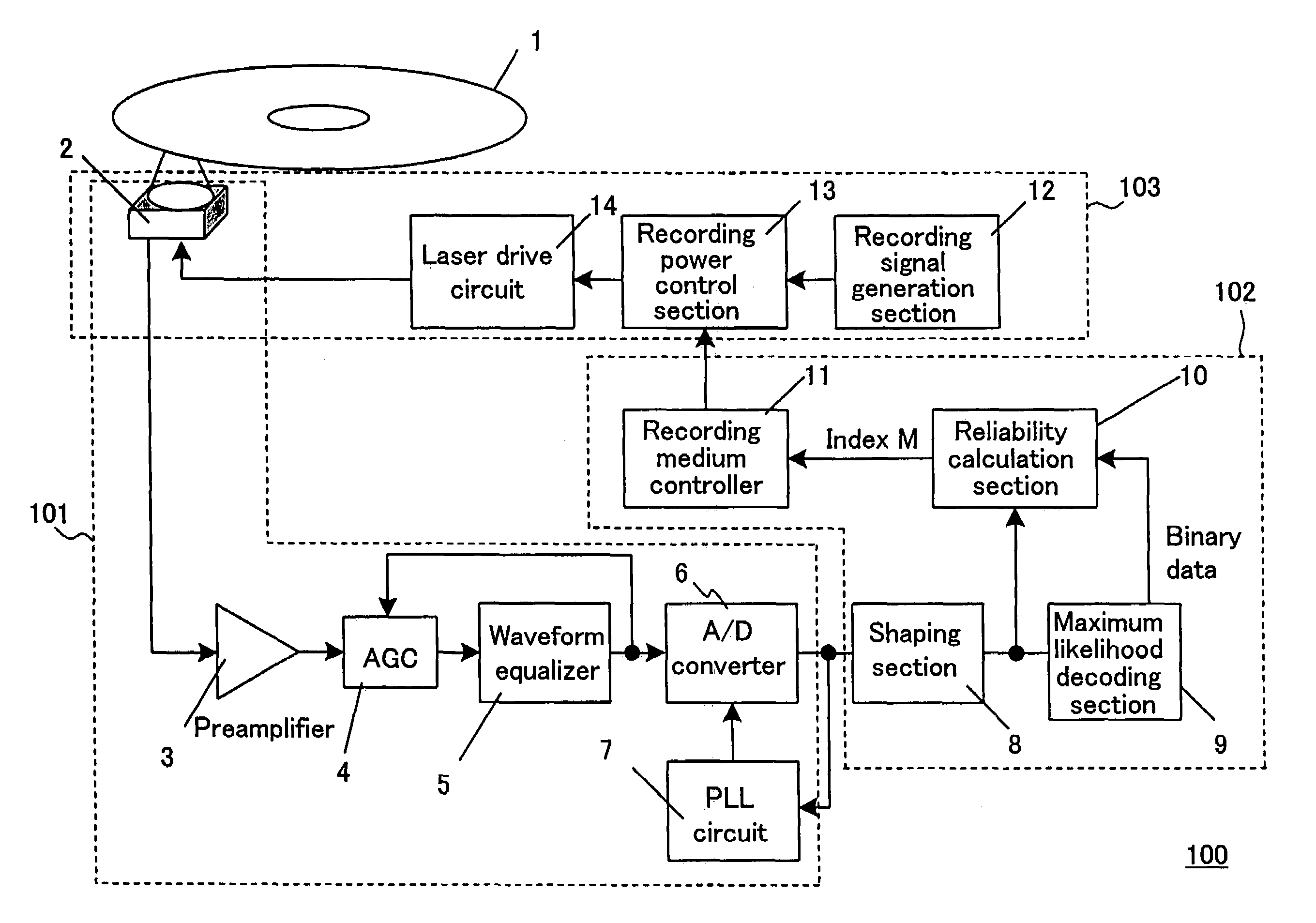
[0091]FIG. 4 shows a recording / reproduction apparatus 100 according to an example of the present invention. The recording / reproduction apparatus 100 includes a reproduction section 101, a recording control device 102, and a recording section 103. On the recording / reproduction apparatus 100, a recording medium 1 can be mounted. A recording medium 1 is used for optical information recording and reproduction, and is, for example, an optical disc.

[0092]The reproduction section 101 includes an optical head section 2, a preamplifier 3, an AGC 4, a waveform equalizer 5, an A / D converter 6, and a PLL circuit 7. The reproduction section 101 generates a digital signal from an analog signal representing information reproduced from the recording medium 1.

[0093]The recording control section 102 includes a shaping section 8, a maximum likelihood decoding section 9, a reliability calculation section 10, and a recording mediu...

embodiment 2

3. Embodiment 2

[0140]3-1. Recording / Reproduction Apparatus of Embodiment 2

[0141]FIG. 10 shows a recording / reproduction apparatus 200 according to Embodiment 2 of the present invention. The recording / reproduction apparatus 200 comprises a recording control device 202 instead of the recording control device 102 of the recording / reproduction apparatus 100 according to Embodiment 1 of the present invention, which is described with reference to FIG. 4. Therefore, in FIG. 10, the same parts as those of the recording / reproduction apparatus 100 of FIG. 4 are referenced with the same reference numerals and will not be explained.

[0142]The recording control device 202 comprises a shaping section 8, a maximum likelihood decoding section 9, a reliability calculation section 10, a recording medium controller 11, and the modulation degree detection circuit 15. The recording control device 202 is produced as, for example, a semiconductor chip.

[0143]The modulation degree detection circuit 15 calcula...

embodiment 3

4. Embodiment 3

[0163]4-1. Recording / Reproduction Apparatus of Embodiment 3

[0164]FIG. 13 shows a recording / reproduction apparatus 300 according to Embodiment 3 of the present invention. The recording / reproduction apparatus 300 comprises a recording control device 302 instead of the recording control device 102 included in the recording / reproduction apparatus 100 of Embodiment 1 of the present invention, which is described with reference to FIG. 4, and a recording section 303 instead of the recording section 103 included in the recording / reproduction apparatus 100. Therefore, in FIG. 13, the same parts as those of the recording / reproduction apparatus 100 of FIG. 4 are referenced with the same reference numerals and will not be explained.

[0165]The recording control device 302 comprises a shaping section 8, a maximum likelihood decoding section 9, a reliability calculation section 10 and a control section 304 (a pattern detection circuit 17, an edge shift detection circuit 18, and a rec...


PUM

PropertyMeasurementUnit
recording poweraaaaaaaaaa
Euclid distanceaaaaaaaaaa
poweraaaaaaaaaa

Abstract

A recording / reproduction apparatus, comprising a first recording section for recording test information onto a medium using at least one recording power, a reproduction section for reproducing at least one test signal indicating the test information from the medium, and a second recording section for recording information onto the medium using one of the at least one recording power. The reproduction section comprises a decoding section for performing maximum likelihood decoding of the at least one test signal and generating at least one binary signal indicating a result of the maximum likelihood decoding, a calculation section for calculating a reliability of the result of the maximum likelihood decoding based on the at least one test signal and the at least one binary signal, and an adjustment section for adjusting a recording power for recording the information onto the medium to the one recording power based on the reliability.

Description

[0001]This nonprovisional application claims priority under 35 U.S.C. §119(a) on Patent Application No. 2003-376855 filed in Japan on Nov. 6, 2003, the entire contents of which are hereby incorporated by reference.BACKGROUND OF THE INVENTION[0002]1. Field of the Invention[0003]The present invention relates to a recording / reproduction apparatus, recording / reproduction method, program, and recording power adjustment apparatus capable of adjusting a recording power (e.g., a write power, an erase power, or a bottom power). More particularly, the present invention relates to a recording / reproduction apparatus, recording / reproduction method, program, and recording power adjustment apparatus capable of adjusting a recording power based on a partial response maximum likelihood (PRML) technique which is a type of reproduction technique.[0004]2. Description of the Related Art[0005]Phase change optical discs (CD-RW, DVD-RAM, DVD-RW, Blu-ray Disc, etc.) are known as rewritable optical discs. Fo...

Claims


Application Information

Patent Timeline
Patent Type & Authority Patents(United States)
IPC IPC(8): G11B7/00G11B7/004G11B7/0045G11B7/005G11B7/007G11B7/125
CPCG11B7/0053G11B7/0062G11B7/00736G11B7/1267G11B7/004
Inventor MIYASHITA, HARUMITSUNAKAJIMA, TAKESHISHOJI, MAMORUHINO, YASUMORI
Owner PANASONIC CORP
Learn More