
Device and method for generating X-rays having different energy levels and material discrimination system

a technology of material discrimination and x-rays, applied in material analysis using wave/particle radiation, instruments, nuclear engineering, etc., can solve the problems of low sensitivity of dual-energy method in distinguishing atomic numbers in high energy range, inability to discriminate material properties of objects under inspection, and inability to distinguish the effective atomic number of substances, etc., to achieve short life and high accuracy

Active Publication Date: 2010-01-12
TSINGHUA UNIV +1
View PDF18 Cites 42 Cited by
  • Summary
  • Abstract
  • Description
  • Claims
  • Application Information

AI Technical Summary

Benefits of technology

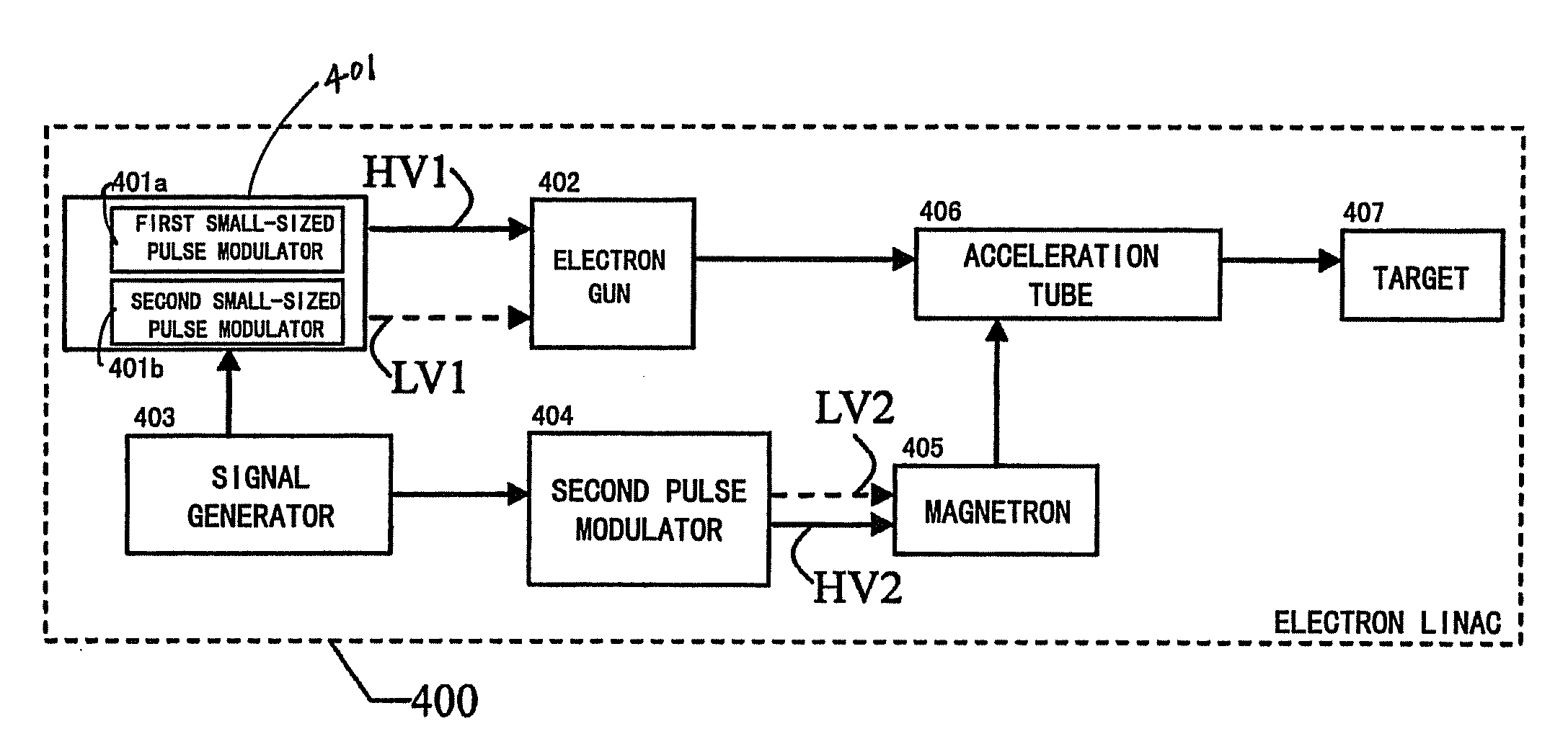
[0007]In view of the above problem with the prior art, the present invention is accomplished. It is an object of the present invention to provide an electron linac for generating X-rays having different energy levels and a method thereof as well as a material discrimination system, which can alternately generate electron beams having different energy spectra, of which the energy levels are distinct from each other, and alternately generate X-rays having different energy spectra by use of electron beam targeting. By causing X-rays of two energy levels to interact with the substance, it is possible to non-destructively inspect large and medium-sized objects and identify the material contained.
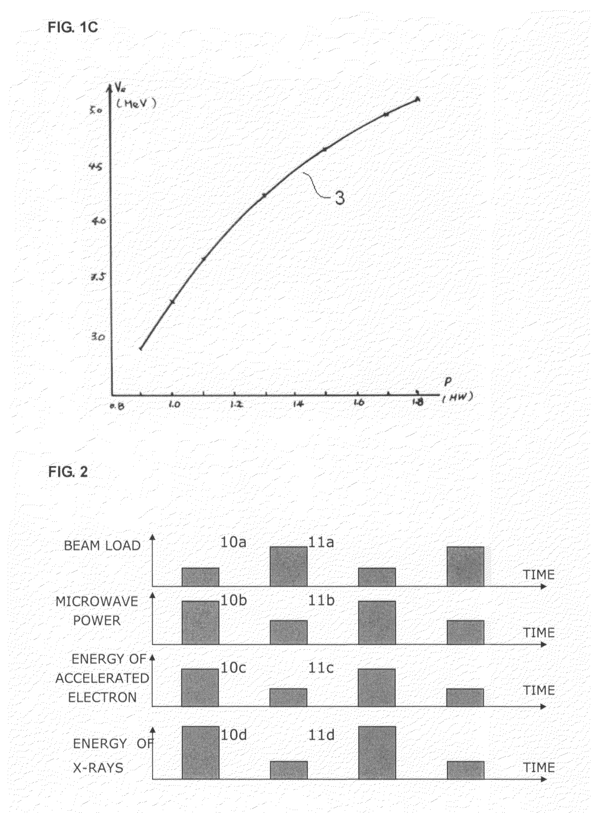
[0018]As a result, the accelerated electron beams having different energy levels can be obtained by changing synchronously the beam load intensity of the accelerator. Meanwhile, the energy level difference between two accelerated electron beams can be further widened by synchronously changing the microwave power fed into the acceleration tube. The X-rays, which result from the targeting by the two electron beams having different energy levels, have a large difference between energy levels, that is, a great distinction between the energy spectra of the two X-ray beams.
[0020]In addition, the alternately generated high-energy X-rays with a large energy difference can implement the material discrimination for large and medium-sized objects with a higher accuracy.
[0021]Further, the present invention realizes a rapid switching between two different energy levels by circuit configuration, thereby overcoming the limitation of the conventional energy switch with a mechanic structure, that is, the mechanic switch has difficulty in rapid switching between two different energy levels and has a short life.

Problems solved by technology

Although such a system can reflect the change in shape and mass thickness of the object under inspection, it can't discriminate the material property of the object under inspection.
However, when X-rays within high energy range (>1 MeV) interact with the substance, electron pair generation and Compton scatter effects predominate, and the relationship between attenuation index corresponding to electron pair generation effect and atomic number is μpair∝Z, which makes the sensitivity of the dual-energy method low in distinguishing atomic numbers in high energy range.
At this time it is impossible to distinguish the effective atomic number of the substance.
If two beams of high-energy X-rays having different original energy levels and spectra are generated respectively by using tow radiation sources in order to identify material, the system will be too complex and costly.
Consequently, it has been considering as impractical to implement large-sized object inspection and material discrimination by the dual-energy method in high energy range.

Method used


Image

  • Device and method for generating X-rays having different energy levels and material discrimination system
  • Device and method for generating X-rays having different energy levels and material discrimination system
  • Device and method for generating X-rays having different energy levels and material discrimination system

Examples


Embodiment Construction

[0031]Hereafter an embodiment of the present invention will be explained in detail with reference to the drawings.

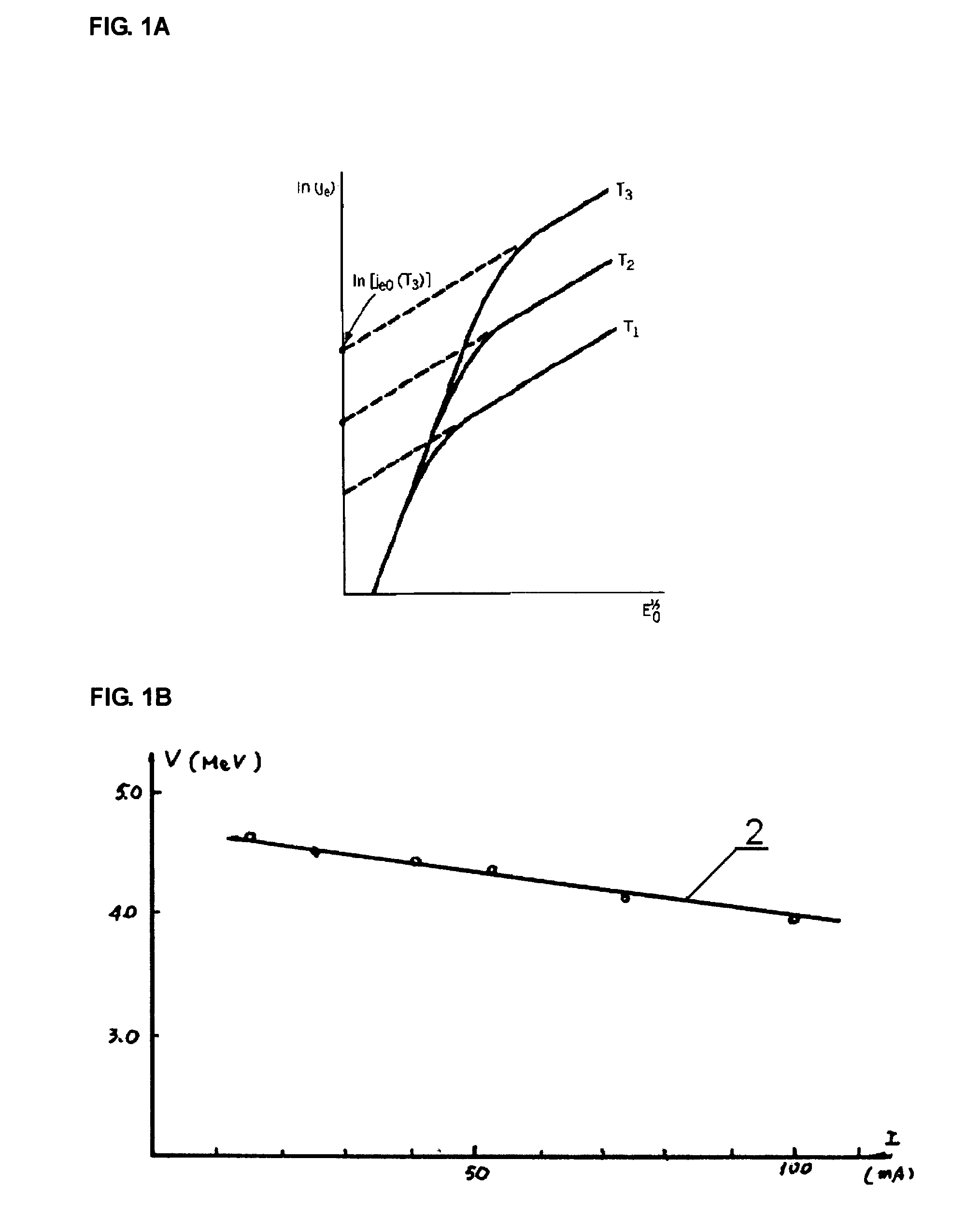
[0032]FIG. 1A shows the electron-emitting characteristic of an electron gun. FIG. 1B is a schematic diagram of accelerated electron energy varying with beam load. FIG. 1C is a schematic diagram of accelerated electron energy varying with fed microwave power. FIG. 2 is a schematic diagram of the parameter relationship between respective main systems of the accelerator while alternately generating X-rays having different energy levels according to an embodiment of the present invention.

[0033]As shown in FIG. 1A, the electron gun has different capabilities of electron emission under different voltage amplitudes. The pulse modulator for driving the electron gun generates high voltages having two different amplitudes, which cause the electron gun to emit electron beams having different current intensities, that is, the obtained electron beams having different beam loads as sh...


PUM


Abstract

Disclosed is a device and method for generating X-rays having different energy levels as well as a material discrimination system thereof. The method comprises the steps of: generating a first pulse voltage, a second pulse voltage, a third pulse voltage and a fourth pulse voltage, generating a first electron beam having a first beam load and a second electron beam having a second beam load, respectively, based on the first pulse voltage and second pulse voltage, generating a first microwave having a first power and a second microwave having a second power, respectively, based on the third pulse voltage and the fourth pulse voltage, accelerating the first and second electron beams respectively using the first and second microwave to obtain the accelerated first electron beam and the second electron beam, hitting a target with the accelerated first electron beam and the second electron beam to generate a first X-ray and a second X-ray having different energy levels. The X-rays having different energy levels generated by the present invention can be used in the non-destructive inspection for large-sized container cargo at places such as Customs, ports and airports, and in realizing the material discrimination for the inspected object.

Description

FIELD OF THE INVENTION[0001]The present invention relates to an electron linac (electron linear accelerator) for radiographic imaging of large and medium-sized objects, more particularly, to an electron linear acceleration device for generating X-rays having different energy levels and a method thereof as well as a material discrimination system, which can discriminate the material contained in the large and medium-sized objects such as cargo or air cargo containers.BACKGROUND OF THE INVENTION[0002]The present application claims priority of Chinese patent application Ser. No. 200610011944.4, filed May 19, 2006, the content of which is hereby incorporated by reference in its entirety.[0003]The existing cargo inspection system based on radiographic imaging generally causes a single energy radiation to interact with the object under inspection, and then detects the radiation having penetrated the object under inspection to obtain an image. Although such a system can reflect the change ...

Claims


Application Information

Patent Timeline
Patent Type & Authority Patents(United States)
IPC IPC(8): H05G1/64H05G2/00
CPCG01N23/087H05G2/00G01N2223/206H05G1/58G01N2223/639G01N23/083G01V5/00H01J35/00H01J35/02
Inventor LIU, YAOHONGTANG, CHUANXIANGCHEN, ZHIQIANGCHEN, HUAIBILIU, JINSHENGGAO, JIANJUN
Owner TSINGHUA UNIV
Learn More