
Power steering system

a technology of steering system and power steering, which is applied in the direction of power steering, vehicle components, and fluid steering, can solve the problems of hydraulic fluid flow limitation, and achieve the effect of preventing the generation of noise or vibration to the steering wheel, and improving the steering feel

Inactive Publication Date: 2010-01-19
HITACHI LTD
View PDF8 Cites 6 Cited by
  • Summary
  • Abstract
  • Description
  • Claims
  • Application Information

AI Technical Summary

Benefits of technology

[0009]An object of the present invention is to provide a power steering system provided with a control device for restraining a noise generated due to excessive flow of hydraulic fluid through a relief valve provided at a pump at transition of a steering wheel from lock end (end of steering state) to returning.
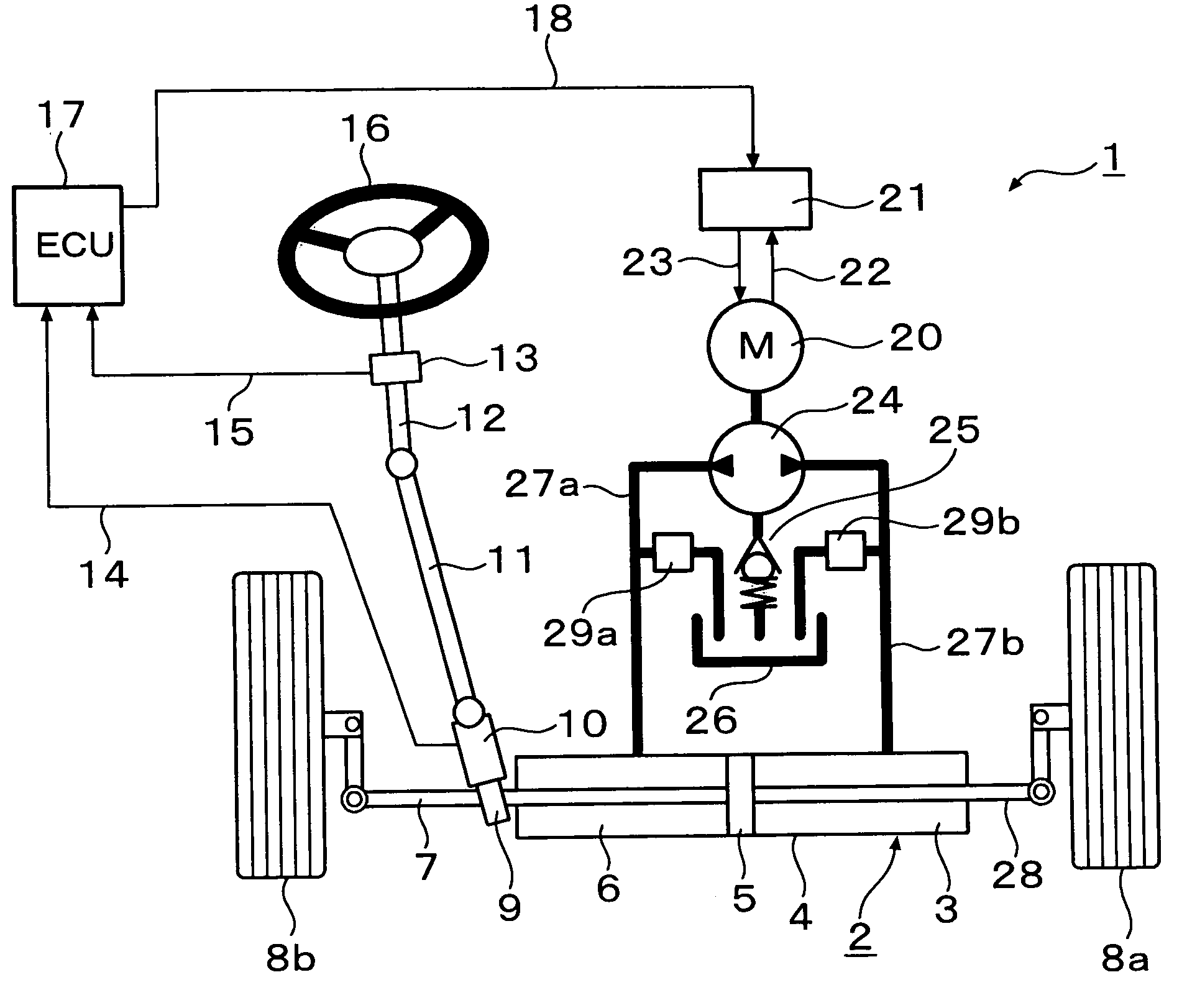
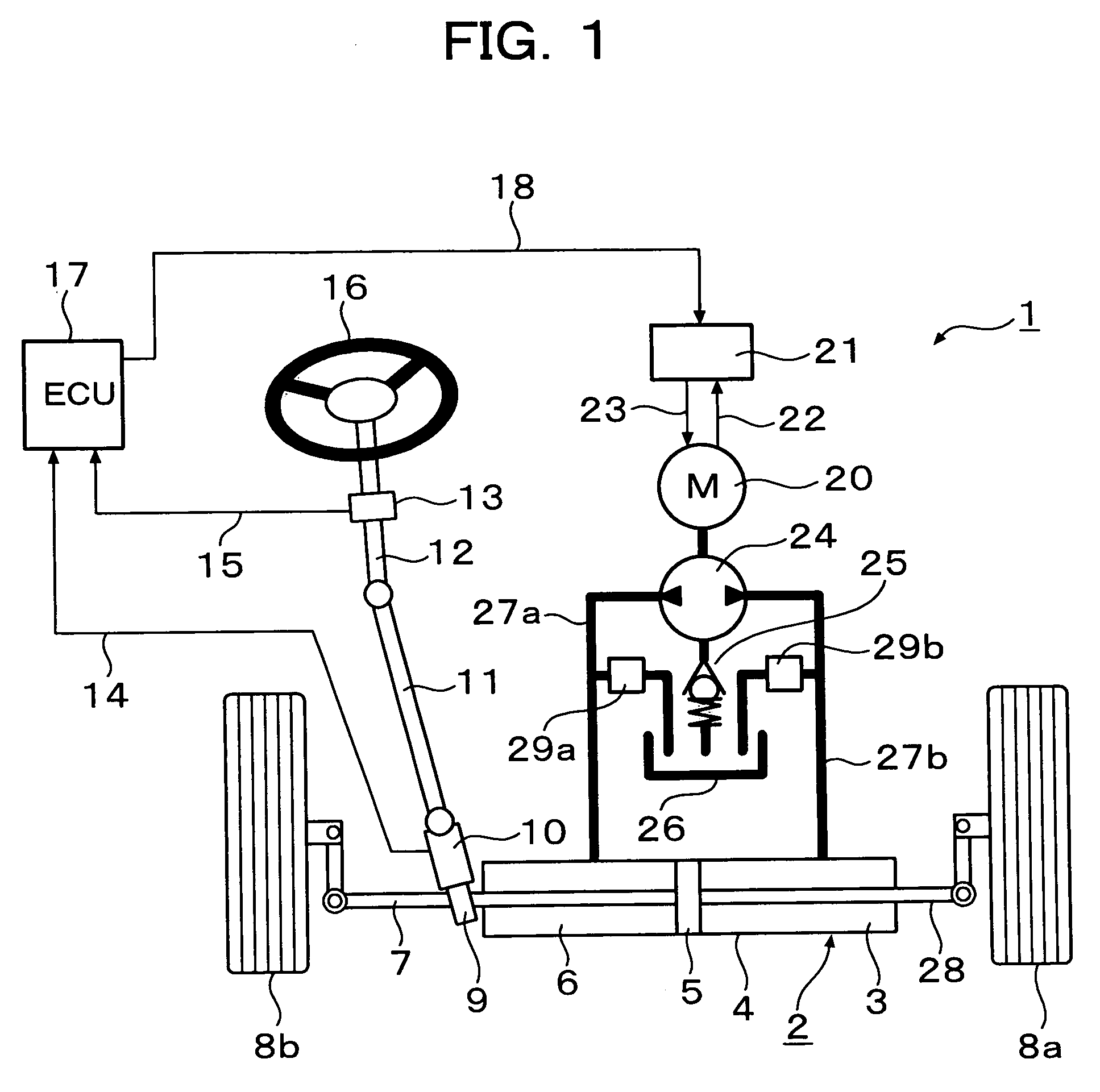
[0011]This is a power steering system provided with a power cylinder for assisting a steering power of a steering mechanism made of a rack and pinion and the like connected to a steering tire, a hydraulic pump having a pair of discharge ports for selectively supplying a hydraulic pressure to both pressure chambers of the power cylinder, a first oil passage and a second oil passage for connecting each of the pair of discharge ports of the hydraulic pump to both the pressure chambers of the power cylinder, respectively, a motor for driving the hydraulic pump, and power steering control means for calculating a command value to the motor based on a steering torque by operation of a steering wheel, in which a flow rate of hydraulic fluid supplied from a high-pressure side oil passage to a low-pressure side oil passage in the first oil passage and the second oil passage is restrained at the end of steering state of the steering mechanism or at transition from lock end to returning.
[0014]According to the present invention, when the steering state of the steering mechanism is ended and transited to returning, the flow rate of the hydraulic fluid flowing from the high-pressure side oil passage to the low-pressure side oil passage is restrained so that an inflow rate of the hydraulic fluid through the relief valve provided at the pump can be rectified. By this, occurrence of a transient fluid flow phenomenon such as surging or water hammer can be restrained, generation of noise or transmission of vibration to a steering wheel can be prevented, and steering feel can be improved.

Problems solved by technology

This flow-rate limitation of the hydraulic fluid is carried out by limiting the flow rate of the hydraulic fluid supplied from the high-pressure side oil passage to the low-pressure side oil passage by providing a valve between each of the first oil passage and the second oil passage and an oil tank and by open-controlling the valve.

Method used


Image

  • Power steering system
  • Power steering system
  • Power steering system

Examples


Embodiment Construction

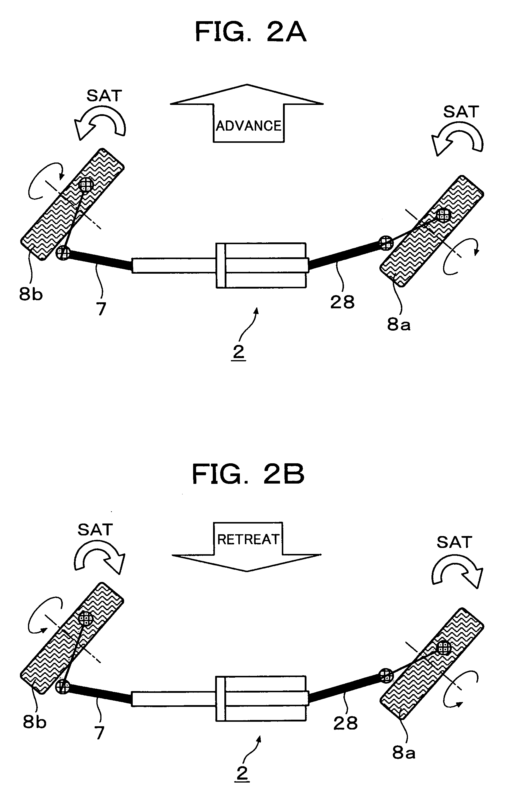
[0027]A power steering system according to an embodiment of the present invention will be described in detail referring to FIGS. 1 to 12. FIGS. 1 to 9 are diagrams for explaining a power steering system according to a first embodiment of the present invention, and FIG. 10 is a diagram for explaining a power steering system according to a second embodiment. FIG. 11 is a diagram for explaining excessive inflow of working oil from a high-pressure side oil passage to a low-pressure side oil passage when a steering state of the steering mechanism in the power steering system according to this embodiment is ended and transited to returning. FIG. 12 is a schematic diagram for explaining a problem to be solved and means for solving the problem in the power steering system according to the embodiment of the present invention.

[0028]FIG. 1 is a diagram showing an entire construction of a power steering system according to the first and the second embodiments of the present invention. FIG. 2 is...


PUM


Abstract

In a power steering system comprising a power cylinder for assisting a steering power of a steering mechanism, a hydraulic pump for supplying a hydraulic pressure to the power cylinder, a first oil passage and a second oil passage connecting the power cylinder and the hydraulic pump respectively, a motor for driving the hydraulic pump, and power steering control means for calculating a command value to the motor based on the steering torque, a flow rate of the working oil supplied from a high-pressure side oil passage to a low-pressure side oil passage is restrained at the transition from the end of the steering state (lock end) of the steering mechanism to the returning. The flow-rate restraint increasingly corrects a driving current of the motor in the steering direction or limits the flow rate of the working oil.

Description

BACKGROUND OF THE INVENTION[0001]1. Field of the Invention[0002]The present invention relates to a power steering system for assisting a steering power of a wheel and to a control device of an electric motor which attempts improvement of a steering feel at lock end of a steering wheel.[0003]2. Related Background of the Invention[0004]As a power assist device for assisting power of a wheel steering according to a steering torque input from a driver, a hydraulic mechanism is usually used. As an example of this prior art, such a technology is proposed that a hydraulic pressure is generated by driving an oil pump using an electric motor and the steering torque inputted from a steering wheel to this generated hydraulic pressure is feedback-controlled so as to generate a steering assist power (See Patent Document 1, for example). With the prior art as shown in Patent Document 1, a steering torque is detected from a value of a torque sensor and the steering assist power is generated accord...

Claims


Application Information

Patent Timeline
Patent Type & Authority Patents(United States)
IPC IPC(8): B62D5/06
CPCB62D5/065
Inventor MIYAJIMA, AYUMUTSUBONO, ISAMUNISHIGAITO, TAKAOMITAKAHASHI, TORUSASAKI, MITSUOSAKAKI, TOSHIMITSUMATSUMURA, TATSUO
Owner HITACHI LTD
Learn More