Torsional vibration damper

a torsional vibration and damper technology, applied in the direction of fluid couplings, gearings, couplings, etc., can solve the problems that the damping curve provided by a tdc can still prove insufficient, and achieve the effect of shortening the travel distance and reducing the stiffness of the first energy storage group

Active Publication Date: 2010-01-19
ZF FRIEDRICHSHAFEN AG
View PDF9 Cites 9 Cited by
  • Summary
  • Abstract
  • Description
  • Claims
  • Application Information

AI Technical Summary

Benefits of technology

[0013]In correspondence with another preferred design of the torsional vibration damper, it is possible to ensure that a predetermined stiffness ratio is obtained between exclusively identical energy-storage devices of preferably the first energy-storage group and the first energy-storage devices of preferably the second energy-storage group. It is advantageous for the first energy-storage group to be designed for a comparatively low stop torque, where this stop torque corresponds to only a fraction of the torque which can be supplied by a drive such as the crankshaft of an internal combustion engine. This means that, when the torque to be transmitted from the drive does not exceed this stop torque, both the first energy-storage group and the second energy-storage group are active, whereas, when the torque to be transmitted is above this value, only the second energy-storage group is active. The advantage of a design such as this is that the stiffness of the first energy-storage group can be made very low, because it does not have to absorb all of the torque which the drive can deliver. For this reason, the first energy-storage group is preferably located radially outside the takeoff-side energy-storage group, and in this way its springs acquire a longer travel distance.
[0015]In still another preferred design of the torsional vibration damper, it can be ensured that a predetermined stiffness ratio is obtained between exclusively identical energy-storage devices of the first energy-storage group and exclusively identical energy-storage devices of the second energy-storage group. One of the energy-storage groups is preferably designed in such a way that its characteristic curve ends at a predetermined first torque value, whereas the characteristic curve of the other energy-storage group ends at a second torque value, wherein the second torque value should be of the order of magnitude of the maximum possible torque which can be transmitted by the drive, such as the crankshaft of an internal combustion engine, and should also be exceeded only slightly by the first torque value. When torque is to be transmitted from the drive in a design of this type, the lower torque value will not be exceeded and thus both energy-storage groups will remain effective as along as the torque to be transmitted from the drive remains just below the maximum possible torque, which means that both groups will remain effective during almost all phases of operation. It is advantageous for the higher torque value to be in the range of 110-120% of the torque which can be delivered by the drive, whereas the lower torque value should be in the range of 80-100% of this torque. The lower torque value is therefore preferably 10-40% less than the higher torque value.
[0017]It may be advantageous in some designs of the torsional vibration damper for the lower torque value to be assigned to the first energy-storage group and for the higher torque value to be assigned to the second energy-storage group. In another case, however, the higher torque value can be assigned to the first energy-storage group, and the lower torque value can be assigned to the second energy-storage group. Nevertheless, in all of the previously mentioned designs of the torsional vibration damper, it is also possible and can be advantageous for the two energy-storage groups to be laid out in the opposite way with respect to each other.

Problems solved by technology

To the extent that the bridging clutch is to be closed even at speeds as low as 1,000 rpm, however, even the damping curve provided by a TDC can still prove insufficient.

Method used


Image

  • Torsional vibration damper
  • Torsional vibration damper
  • Torsional vibration damper

Examples


Embodiment Construction

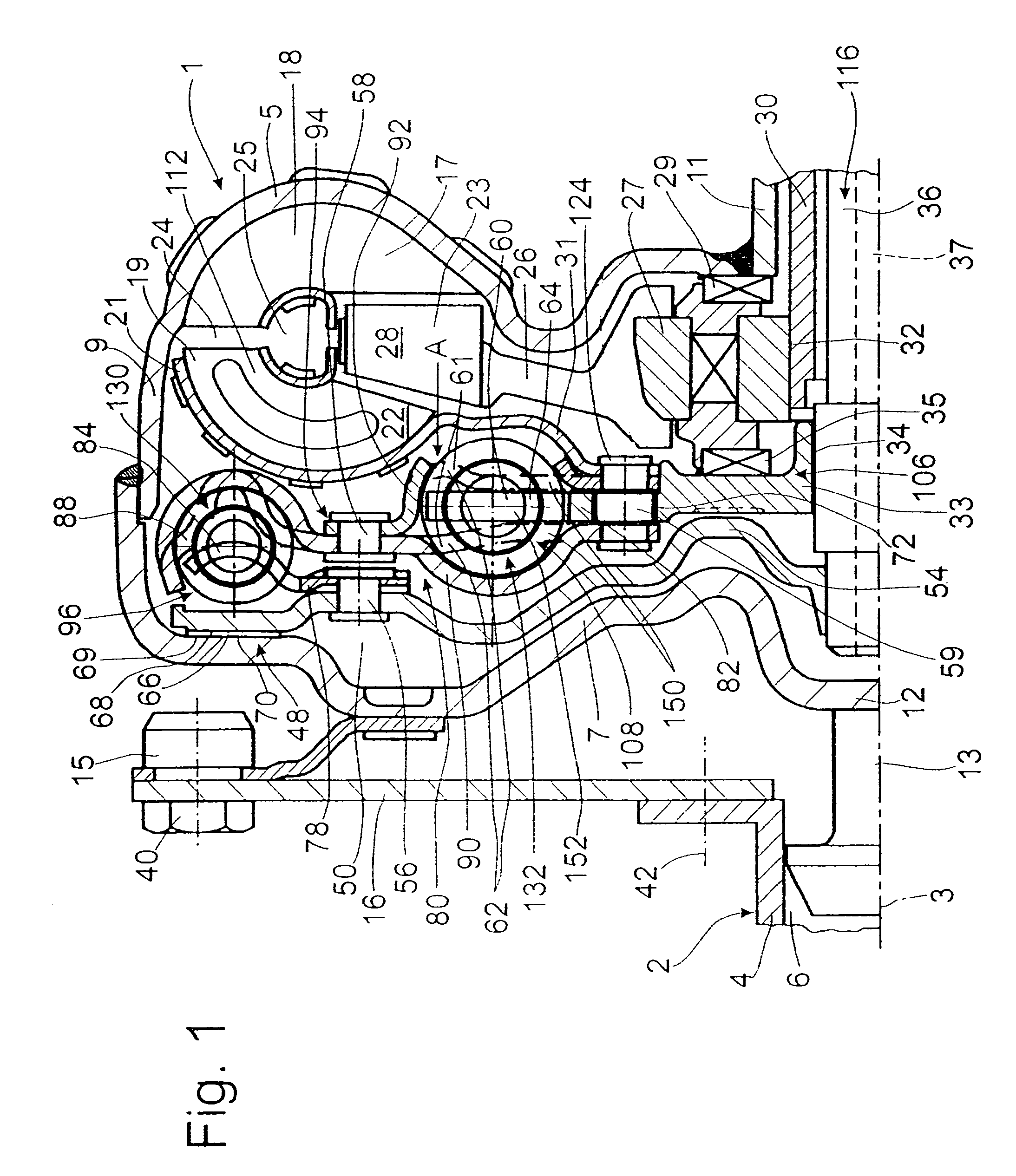
[0033]FIG. 1 shows a hydrodynamic clutch arrangement 1 in the form of a hydrodynamic torque converter, which is able to rotate around an axis of rotation 3. The hydrodynamic clutch arrangement 1 has a clutch housing 5, which, on the side facing a drive 2, such as the crankshaft 4 of an internal combustion engine, has a housing cover 7, which is permanently connected to a pump wheel shell 9. This shell 9 merges in its inner radial area with a pump wheel hub 11.

[0034]The housing cover 7 has in the radially inner area a journal hub 12 carrying a bearing journal 13. In a manner known, the bearing journal 13 is mounted in a recess 6 in the crankshaft 4 to center the clutch housing 5 on the drive side. The housing cover 7 also has a mounting receptacle 15, which is used to attach the clutch housing 5 to the drive 2, namely, by way of the flexplate 16. This flexplate 16 is attached to the mounting receptacle 15 by means of fastening elements 40 and to the crankshaft 4 by means of fastening...


PUM


Abstract

A torsional vibration damper for a bridging clutch of a hydrodynamic clutch arrangement has a drive-side damping device, which can be brought into working connection with the housing of the clutch arrangement and is provided with a drive-side transmission element, which acts via a drive-side energy-storage group on an intermediate transmission element, and a takeoff-side damping device, which uses a takeoff-side group of energy-storage devices to establish a working connection between the intermediate transmission element and a takeoff-side transmission element, which is connected to a takeoff-side component of the hydrodynamic clutch arrangement. A predetermined stiffness ratio is obtained between the energy-storage devices of a first group and the energy-storage devices of a second group, and the energy-storage devices of the drive-side group have a stiffness different from that of the assigned energy-storage devices of the takeoff-side group.

Description

BACKGROUND OF THE INVENTION[0001]The invention pertains to a torsional vibration damper on a bridging clutch of a hydrodynamic clutch arrangement.[0002]A torsional vibration damper of this type is known from, for example, U.S. Pat. No. 7,073,646. The hydrodynamic clutch arrangement, realized in the form of a torque converter, is designed with a bridging clutch. The side of the clutch piston facing the clutch housing is provided with a friction surface, by means of which the piston can be brought into frictional connection by way of an intermediate plate with an opposing friction surface on the clutch housing. The bridging clutch establishes a working connection between the clutch housing, which is attached nonrotatably to a drive such as the crankshaft of an internal combustion engine, and the torsional vibration damper. That is, the connection is established between the clutch housing and a drive-side transmission element of the torsional vibration damper, this transmission element...

Claims


Application Information

Patent Timeline
Patent Type & Authority Patents(United States)
IPC IPC(8): F16D47/02F16D3/66F16D33/00F16D47/06F16H45/02
CPCF16F15/12366F16H45/02F16H2045/007F16H2045/0226F16H2045/0231F16H2045/0247
Inventor WACK, ERWINSASSE, CHRISTOPHSUDAU, JORG
Owner ZF FRIEDRICHSHAFEN AG
Why Eureka
Try Eureka