Valve prosthesis

a valve and prosthesis technology, applied in the field of valve prosthesis, can solve the problems of poor opening, heart failure, reducing the flow of blood, etc., and achieve the effect of putting back into condition easily

Active Publication Date: 2010-01-19
WL GORE & ASSOC INC
View PDF18 Cites 94 Cited by
  • Summary
  • Abstract
  • Description
  • Claims
  • Application Information

AI Technical Summary

Benefits of technology

[0016]An object of the invention is to propose a valve prosthesis that can be put back into condition easily by means of an endoluminal approach.
[0031]the carrier structure includes at its surface a textile sheet making suturing possible.

Problems solved by technology

In particular, they can suffer from poor opening, thus reducing the flow of blood, or from being somewhat leaky, thus allowing a reflux or regurgitation of blood back into the ventricle that has just expelled it.
These regurgitation problems lead to abnormal expansion of the ventricle thereby producing, in the long run, heart failure.
It is found that after such a prosthesis has been implanted for several years, it degenerates and no longer functions efficiently.
In particular, the flexible shutter tears and presents holes, or the shutter becomes calcified and thus loses flexibility, thus no longer being capable of deforming to perform its valve function.
However, it is not possible to remove the old prosthesis via an endoluminal path, in particular because the carrier structure of the prosthesis is sutured to the wall of the heart, meaning that they cannot be separated without major surgery for complete replacement of the valve.
Putting the new valve into place and deploying it are operations that are very difficult, particularly when the old prosthesis is very damaged.

Method used


Image

  • Valve prosthesis
  • Valve prosthesis
  • Valve prosthesis

Examples


Embodiment Construction

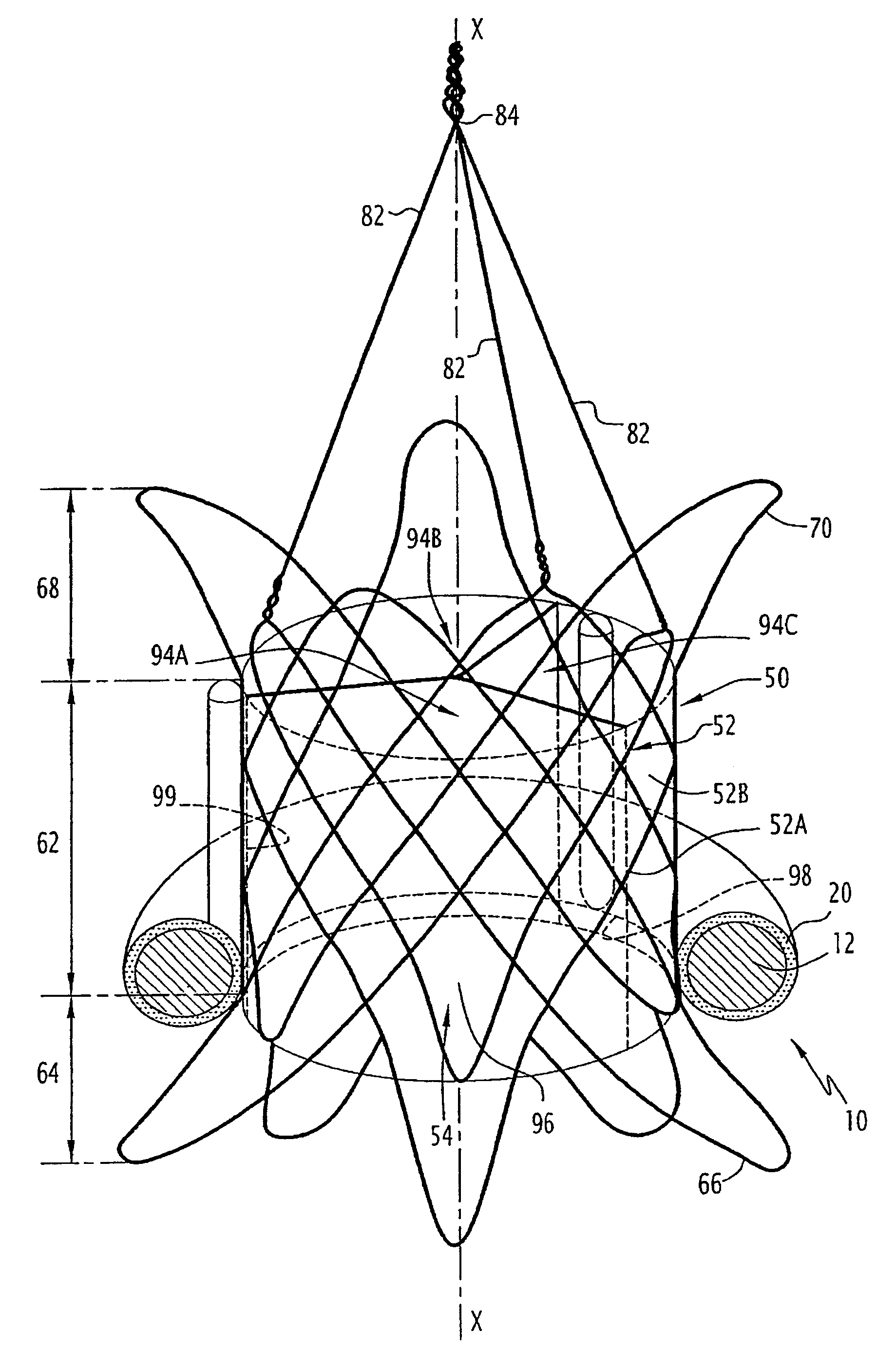
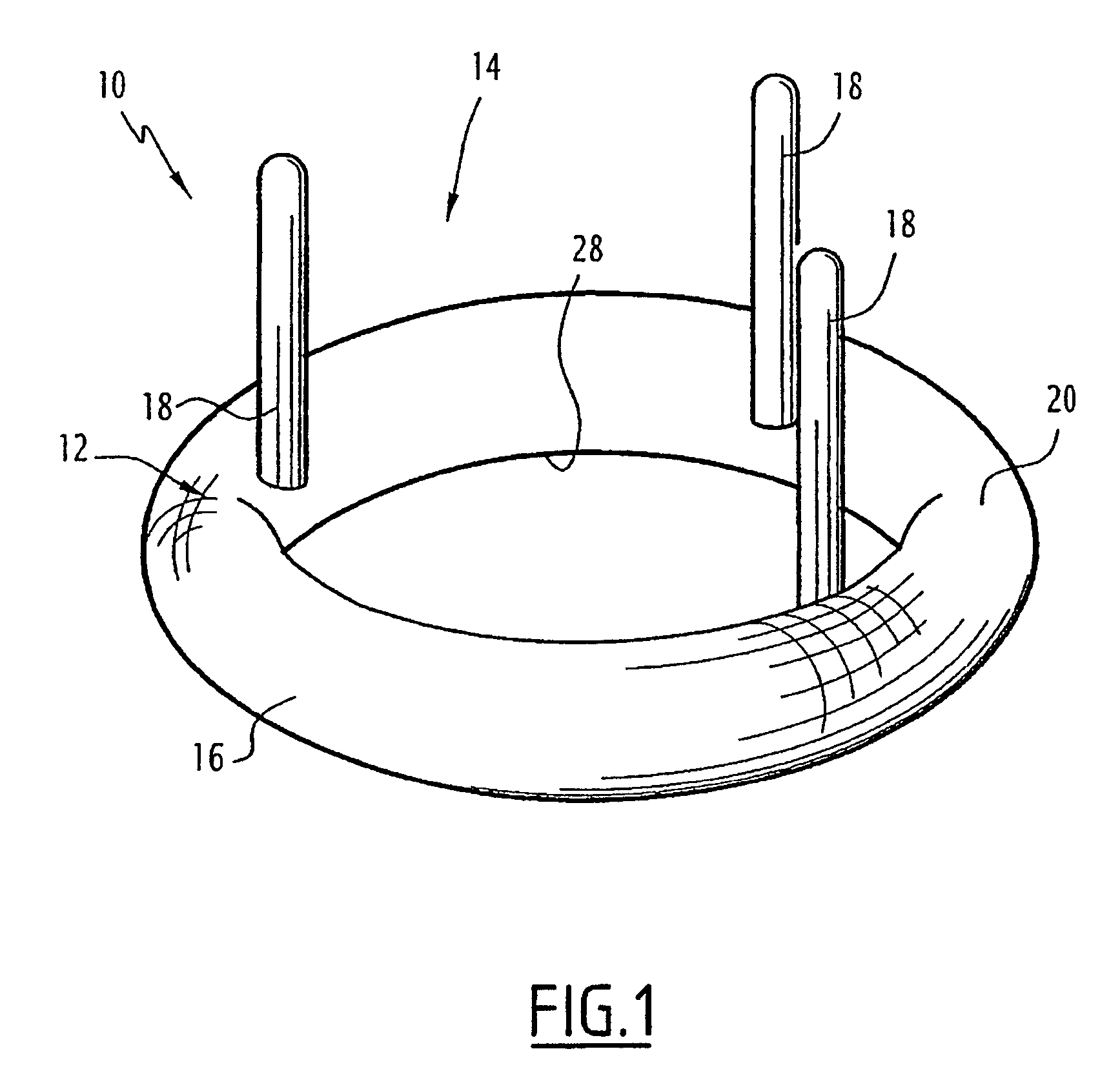
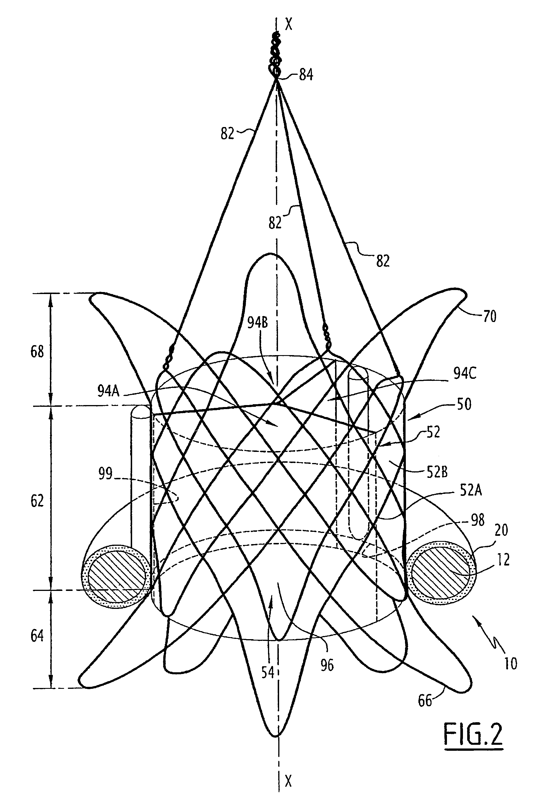
[0042]In FIGS. 1 and 2, a valve prosthesis 10 that can be seen in full in FIG. 2 and only in part in FIG. 1. The valve prosthesis is for an aortic valve of the heart. Thus, this prosthesis is placed immediately upstream from the aorta at the location of the natural valve.

[0043]The valve prosthesis includes a carrier structure 12 that can be seen on its own in FIG. 1. This structure essentially comprises a rigid ring 16 carrying three rigid pegs 18, each extending from the ring parallel to the axis of the ring 16. This ring is constituted by a rigid metal torus having the three pegs 18 welded thereto. The torus is covered over its entire surface in a woven textile sheet 20 enabling the carrier structure to be secured to the tissue of the heart by suturing the textile sheet to the wall of the heart. The inside diameter of the ring 16 lies in the range 15 millimeters (mm) to 40 mm.

[0044]Each peg 18 has one end secured to ring 16, and all of them project from the same side of the ring. ...


PUM


Abstract

A valve prosthesis includes a flexible plug and an annular bearing reinforcement which is embodied such that it is radially rigid and surgically implantable in the area of a heart valve. The valve prosthesis is provided with an interchangeable prosthetic valve, is independent of the bearing reinforcement, endoluminally placeable and includes a tubular support which is radially deformable between a folded setting position and an unfolded position for implanting into a bearing structure and the flexible plug connected to a tubular support. The bearing reinforcement forms an annular support devoid of any plug capable of univocally limiting a blood flow circulation.

Description

BACKGROUND OF THE INVENTION[0001]The present invention relates to a valve prosthesis to be put into place by an endoluminal approach. The prosthesis is the type comprising a flexible shutter and an annular carrier structure that is radially rigid and suitable for being surgically implanted at the location of a heart valve.[0002]The heart comprises two atriums and two ventricles which are separated by valves. Valves are also present at the outlets from the right ventricle (pulmonary valve) and from the left ventricle (aortic valve).[0003]These valves ensure that blood flows in one direction only, avoiding reflux of blood at the end of ventricular contraction.[0004]Valves can suffer diseases. In particular, they can suffer from poor opening, thus reducing the flow of blood, or from being somewhat leaky, thus allowing a reflux or regurgitation of blood back into the ventricle that has just expelled it.[0005]These regurgitation problems lead to abnormal expansion of the ventricle thereb...

Claims


Application Information

Patent Timeline
Patent Type & Authority Patents(United States)
IPC IPC(8): A61F2/06A61F2/24A61F2/90
CPCA61F2/2409A61F2/2418A61F2/90A61F2230/0078A61F2220/005A61F2220/0058A61F2230/0054A61F2220/0008
Inventor STYRC, MIKOLAJ WITOLD
Owner WL GORE & ASSOC INC
Why Eureka
Try Eureka