Zoom lens and image pick-up apparatus
a pickup apparatus and zoom lens technology, applied in the field of new zoom lens and novel image pickup apparatus, can solve the problems of difficult realization of a broader angle, small magnification ratio, difficult realization of high magnification, etc., and achieve the effect of reducing color aberration, high optical performance, and high optical performan
- Summary
- Abstract
- Description
- Claims
- Application Information
AI Technical Summary
Benefits of technology
Problems solved by technology
Method used
Image

Examples
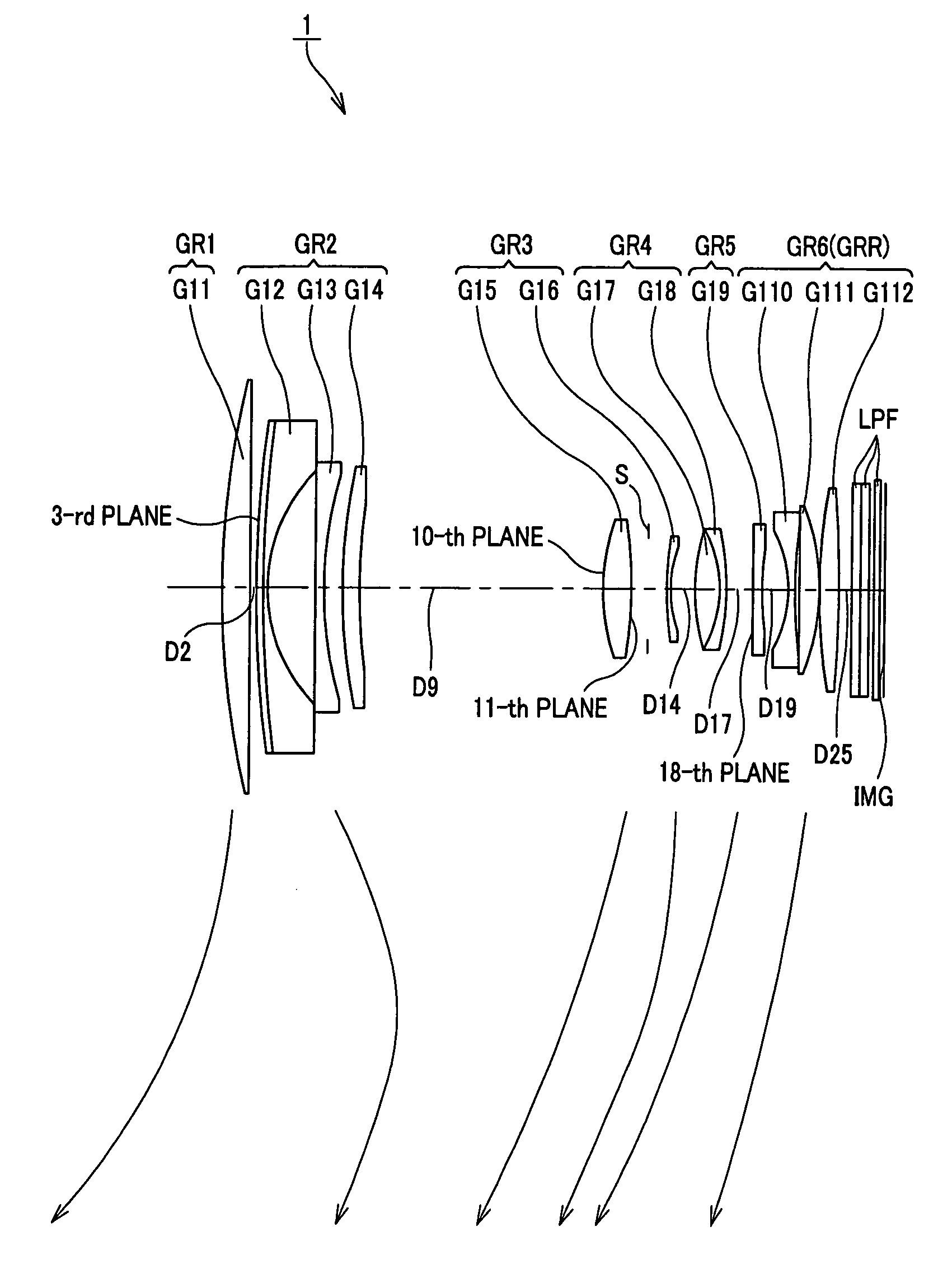
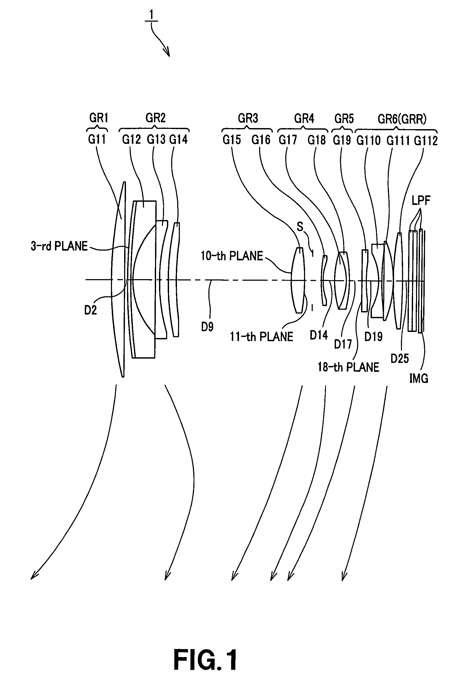
embodiment 1
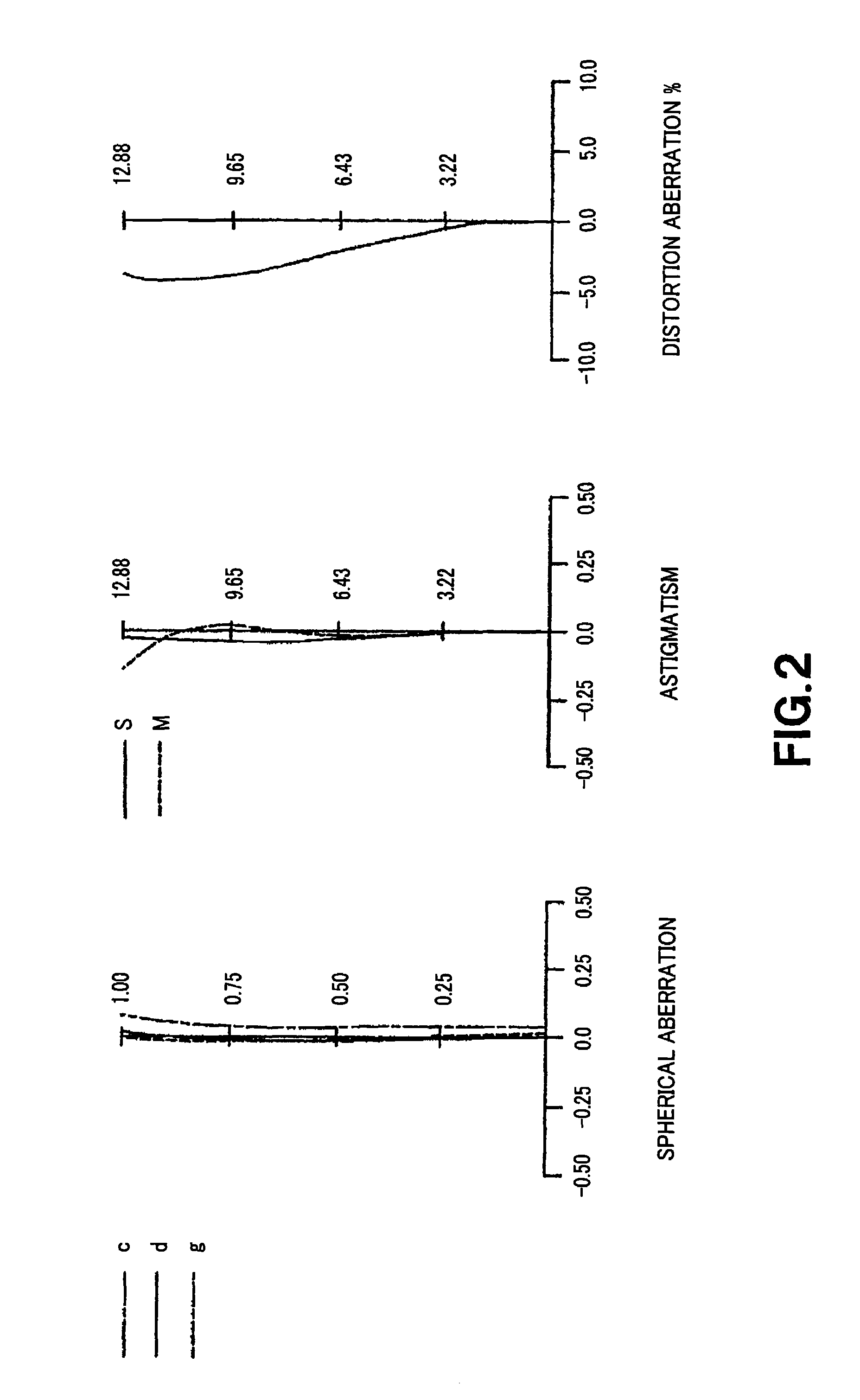
[0084]Various aberration diagrams in the infinity far in-focus state of the numeric value embodiment 1 are respectively shown in FIGS. 2 to 4. FIG. 2 shows various aberration diagrams at the wide-angle end state (f=14.73), FIG. 3 shows various aberration diagrams at the intermediate focal length (f=32.05) between the wide-angle end state and the telescopic end state, and FIG. 4 shows various aberration diagrams at the telescopic end state (f=69.71).
[0085]In the respective aberration diagrams of FIGS. 2 to 4, in the case of spherical aberration, a ratio with respect to open F value is taken on the ordinate and defocus is taken on the abscissa, wherein a solid line indicates a d line, a single-dotted lines indicate C line, and dotted lines indicate spherical aberration. In the case of astigmatism, the ordinate indicates image height, the abscissa indicates focus, the solid line S indicates a sagittal image surface, and dotted lines M indicate meridional image surface. In the case of d...
embodiment 2
[0095]Various aberration diagrams in the infinity far in-focus state of the numerical value embodiment 2 are respectively shown in FIGS. 6 to 8. FIG. 6 shows various aberration diagrams at the wide-angle end state (f=14.42), FIG. 7 shows various aberration diagrams at the intermediate focal length (f=31.37) between the wide-angle end state and the telescopic end state, and FIG. 8 shows various aberration diagrams at the telescopic end state (f=68.25).
[0096]In the respective aberration diagrams of FIGS. 6 to 8, in the case of the spherical aberration, a ratio with respect to an open F value is taken on the ordinate and defocus is taken on the abscissa, wherein a solid line indicates a d line, single dotted lines indicate a C line, and a dotted line indicates spherical aberration at a g line. In the case of astigmatism, the ordinate indicates image height, the abscissa indicates focus, solid line S indicates sagittal image surface, and dotted lines M indicate meridional image surface....
embodiment 3
[0106]Various aberration diagrams in the infinity far in-focus state of the numerical value embodiment 3 are respectively shown in FIGS. 10 to 12, wherein FIG. 10 shows various aberration diagrams at the wide-angle end state (f=12.10), FIG. 11 shows various aberration diagrams at the intermediate focal length (f=24.20) between the wide-angle end state and the telescopic end state, and FIG. 12 shows various aberration diagrams at the telescopic end state (f=48.40).
[0107]In the respective aberration diagrams of FIGS. 10 to 12, in the case of spherical aberration, a ratio with respect to an open F value is taken on the ordinate, and defocus is taken on the abscissa, wherein solid line indicates spherical aberration at a d line, single dotted lines indicate spherical aberration at a C line, and a dotted line indicates spherical aberration at a g line. In the case of astigmatism, the ordinate indicates image height, the abscissa indicates focus, solid line S indicates a sagittal image su...
PUM
 Abstract
Description
Claims
Application Information