Paper conveyance apparatus

a paper conveyancing and apparatus technology, applied in the direction of article delivery, thin material handling, article separation, etc., to achieve the effect of stable paper feeding quality, reduced paper conveyancing speed, and low variation in the stopping position of paper

Inactive Publication Date: 2010-01-26
RICOH KK
View PDF26 Cites 11 Cited by
  • Summary
  • Abstract
  • Description
  • Claims
  • Application Information

AI Technical Summary

Benefits of technology

[0013]The present invention has been designed in consideration of these circumstances, and it is a first object thereof to provide a paper conveyance apparatus which is capable of conveying paper in an identical manner to paper supplied from a main body feeding table, regardless of the paper size, by reducing the paper conveyance speed at which paper is conveyed from an intermediate conveyance portion during conveyance of the paper such that the leading edge of the paper is stopped in a predetermined stopping position, thereby obtaining a stable paper feeding quality with little variation in the stopping position of the paper, and which is capable of preventing damage to the leading edge of the paper caused by contact with a main body separating roller, for example, when the paper advances too far, and jams caused by deformation of the paper.
[0014]In addition to the first object, a second object of the present invention is to provide a paper conveyance apparatus which is capable of obtaining an even more stable paper feeding quality with even less variation in the stopping position of the paper, and of preventing deviation in the stopping position of the paper caused by slight oscillation or external force, particularly with small-sized paper having a short length, by reducing the paper conveyance speed at which paper is conveyed from the intermediate conveyance portion during conveyance of the paper in order to reduce inertia, and also applying a braking force or a load directly to the paper using a braking force applying device such as an elastic member.
[0015]In addition to the first and second objects, a third object of the present invention is to provide a paper conveyance apparatus which, as well as exhibiting effects to be described below, is capable of preventing skew generated when small-sized paper having a short length in particular is conveyed. When such short paper is conveyed, the trailing edge of the paper is not held down by a paper conveyance device, or else the length by which the paper is held down by the paper conveyance device is short, and hence if the elastic member is not located in a position of substantially linear symmetry in relation to the center line of the paper width direction when in contact with the paper, the braking force and load / pressure which act on the paper vary, causing such skew.

Problems solved by technology

When such short paper is conveyed, the trailing edge of the paper is not held down by a paper conveyance device, or else the length by which the paper is held down by the paper conveyance device is short, and hence if the elastic member is not located in a position of substantially linear symmetry in relation to the center line of the paper width direction when in contact with the paper, the braking force and load / pressure which act on the paper vary, causing such skew.

Method used


Image

  • Paper conveyance apparatus
  • Paper conveyance apparatus
  • Paper conveyance apparatus

Examples


first specific example

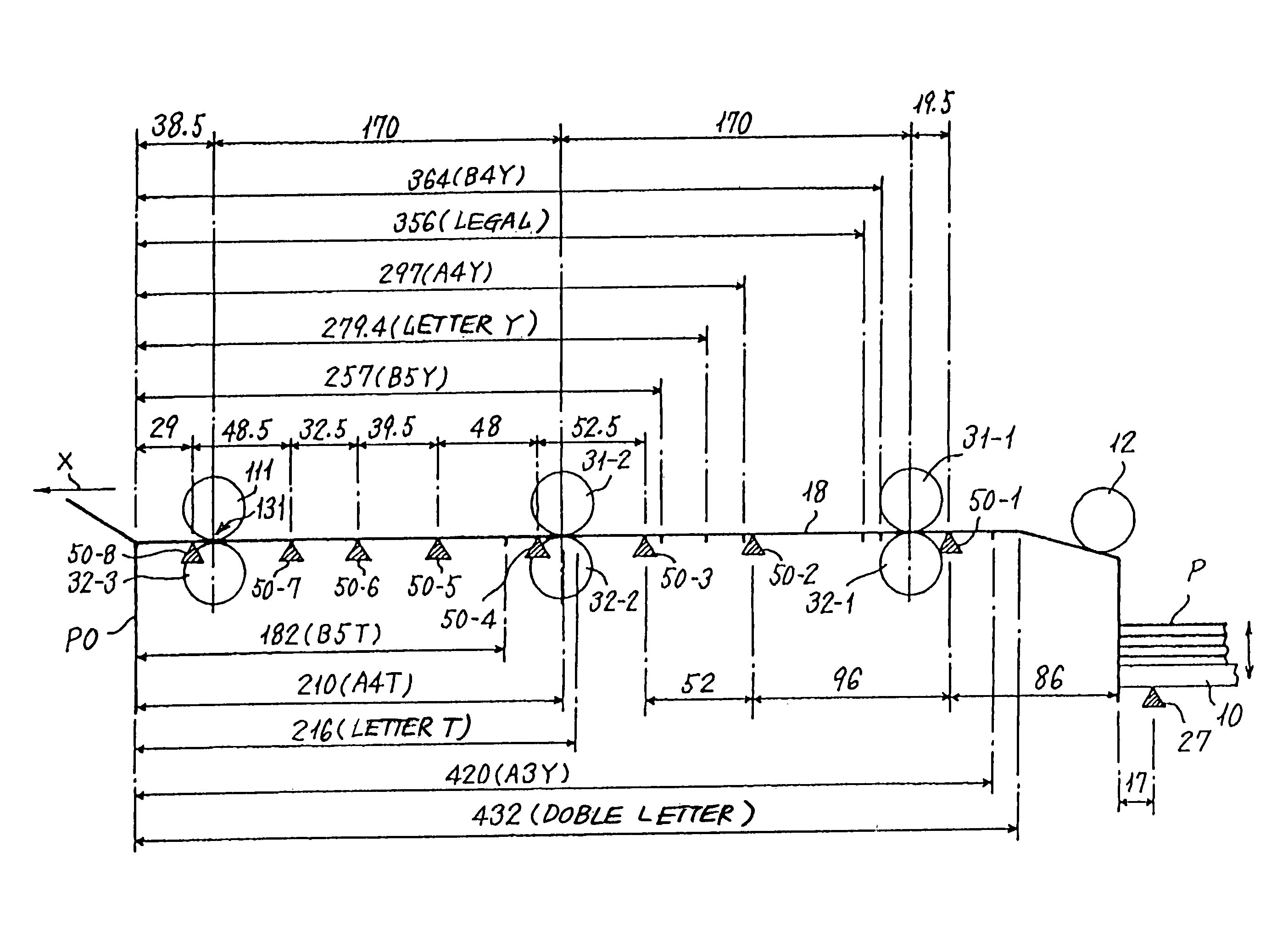
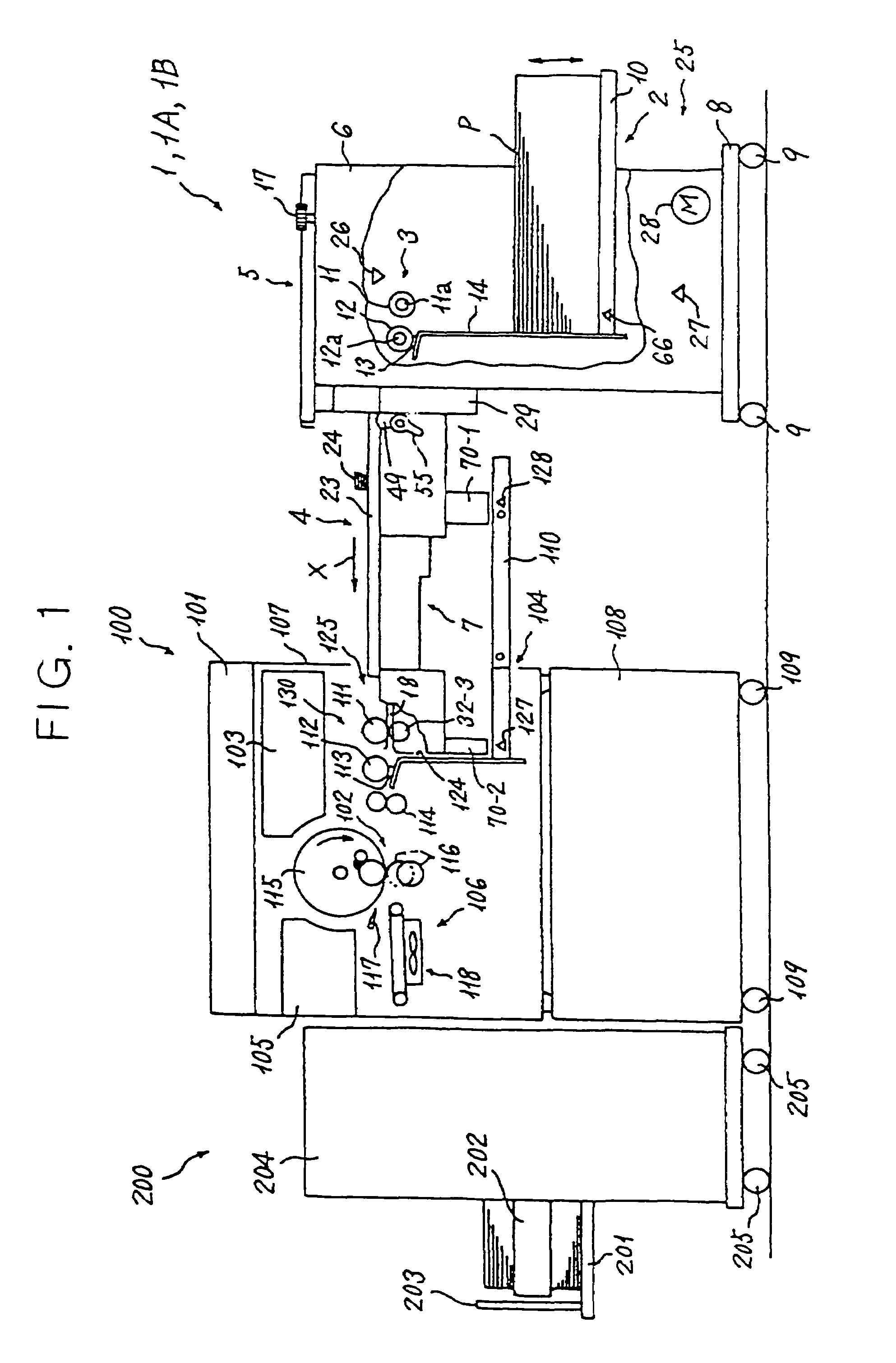
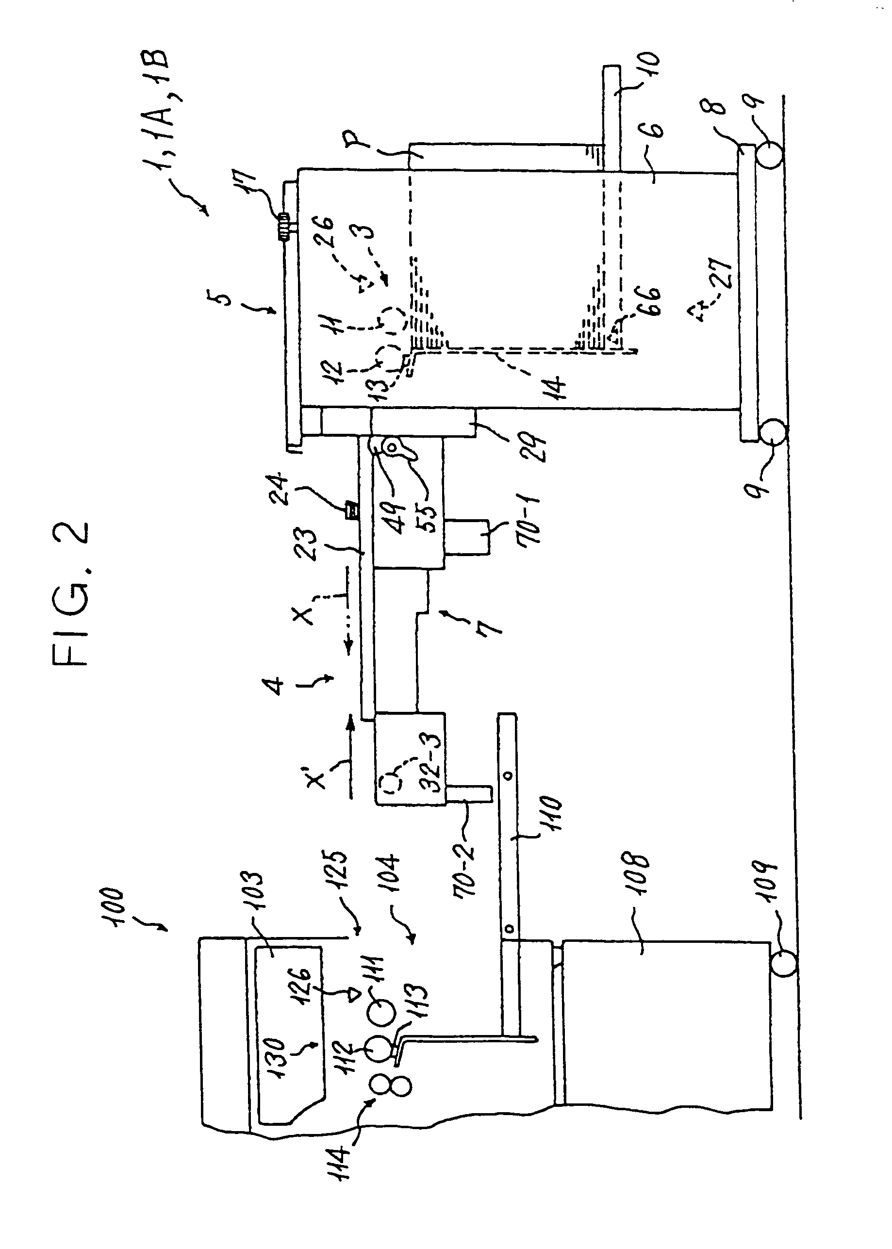
[0274]A bulk feed / conveyance unit 1A serving as a paper conveyance apparatus pertaining to a first specific example of the present invention is shown in FIGS. 1 to 4 and 33. The bulk feed / conveyance unit 1A differs mainly from the bulk feed / conveyance unit 1 of the unpublished embodiment shown in FIGS. 1 through 32A and 32B in that the control apparatus 85 (CPU 86) is allocated a third function for performing the paper conveyance control to be described below.

[0275]The control apparatus 85 (CPU 86) comprises a third function as a control device for reducing the paper conveyance speed of the second paper conveyance device 30-2 and third paper conveyance device 30-3, disposed to the front and rear of the seventh sensor 50-7, when the leading edge of the paper P is detected by the seventh sensor 50-7, which is disposed one sensor further toward the upstream side of the intermediate conveyance path 18 than the eighth sensor 50-8, which is the furthest-downstream paper detecting device. ...

second specific example

[0283]A bulk feed / conveyance unit 1B serving as a paper conveyance apparatus pertaining to a second specific example of the present invention is shown in FIGS. 1 to 4 and 33 to 37. The bulk feed / conveyance unit 1B differs mainly from the bulk feed / conveyance unit 1A shown in FIGS. 1 to 4 and 33 in that a pair of plate springs 132 constituted by elastic members and serving as a braking force applying device for applying a braking force to the conveyed paper P are annexed to the rear end portion of the auxiliary upper guide plate 36, disposed on the intermediate conveyance path 18 between the eighth sensor 50-8 and the seventh sensor 50-7, which is disposed one sensor further toward the upstream side of the intermediate conveyance path 18 than the eighth sensor 50-8, as shown in FIGS. 34 through 37 and as will be described below.

[0284]As shown in FIGS. 34 to 37, each plate spring 132 is adhered and fixed to the rear surface of an upward-facing inclined portion on the rear end portion ...


PUM


Abstract

A paper conveyance apparatus includes a stacking portion; a feeding mechanism to extract and feed paper from the stacking portion one sheet at a time; and an intermediate portion for conveying the fed paper to the vicinity of a feeding port or feeding device of a main body of an image forming apparatus. The intermediate portion includes a plurality of conveyance devices and a plurality of paper detecting devices disposed from the upstream side to the downstream side of a conveyance path. The paper conveyance apparatus further includes a control device for reducing the conveyance speed of the plurality of conveyance devices when the leading edge of the paper is detected by a detecting device disposed at least one device further toward the upstream side than a paper detecting device disposed furthest downstream of the plurality of detecting devices.

Description

BACKGROUND OF THE INVENTION[0001]1. Field of the Invention[0002]The present invention relates to a paper conveyance apparatus, including a bulk feeding apparatus having an intermediate conveyance portion for feeding a sheet-form recording medium (paper) on which an image is to be formed to an image forming apparatus such as a copier, printing machine, facsimile apparatus, printer, or plotter.[0003]2. Description of the Background Art[0004]In image forming apparatuses such as copiers, printing machines, facsimile apparatuses, printers including ink jet printers, and plotters, there is typically an upper limit of several hundred sheets to the paper stacking capacity (the number of sheets of paper that can be stacked) of a paper feeding apparatus provided in the main body of the image forming apparatus. Among such image forming apparatuses, an image forming apparatus such as a printing machine, especially a stencil printing machine or offset printing machine, differs from a copier or t...

Claims


Application Information

Patent Timeline
Patent Type & Authority Patents(United States)
IPC IPC(8): B65H7/02B65H5/06B65H5/00B65H5/34
CPCB65H5/00B65H5/34B65H2511/10B65H2513/10B65H2557/63B65H2701/1311B65H2701/1313B65H2220/03B65H2220/01B65H2220/02
Inventor SATOH, KEIICHITAKAHASHI, MITURUARASEKI, YOSHIYUKIOSADA, TOMOTAKA
Owner RICOH KK
Why Eureka
Try Eureka