Ceiling vent air diverter

a ceiling vent and air diverter technology, applied in ventilation systems, lighting and heating apparatus, heating types, etc., can solve the problems of difficult to please everyone all the time, difficult to achieve the effect of reducing the cost of equipment and reducing the cost of finished products

Inactive Publication Date: 2010-01-26
PATHSUPPLY INC
View PDF36 Cites 100 Cited by
  • Summary
  • Abstract
  • Description
  • Claims
  • Application Information

AI Technical Summary

Benefits of technology

[0029]A final object is the ease of manufacture using the vacuum forming procedure which is well know in the art and the tooling is relatively inexpensive permitting the finished product to be economical. Further the discharge air slots in the sides are cut after the molding process is completed permitting omission of some slots in specific sides in special factory orders.

Problems solved by technology

As stated previously a problem has existed for some time that many people find direct air impingement from an air conditioning system to be unpleasant as the air movement or draft is irritating causing the temperature to feel to the person either much colder or hotter than the surrounding environment.
While much time and effort has been applied in the past to optimize the comfort level of the occupants of a building it is impossible to please everyone all of the time.

Method used


Image

  • Ceiling vent air diverter
  • Ceiling vent air diverter
  • Ceiling vent air diverter

Examples


second embodiment

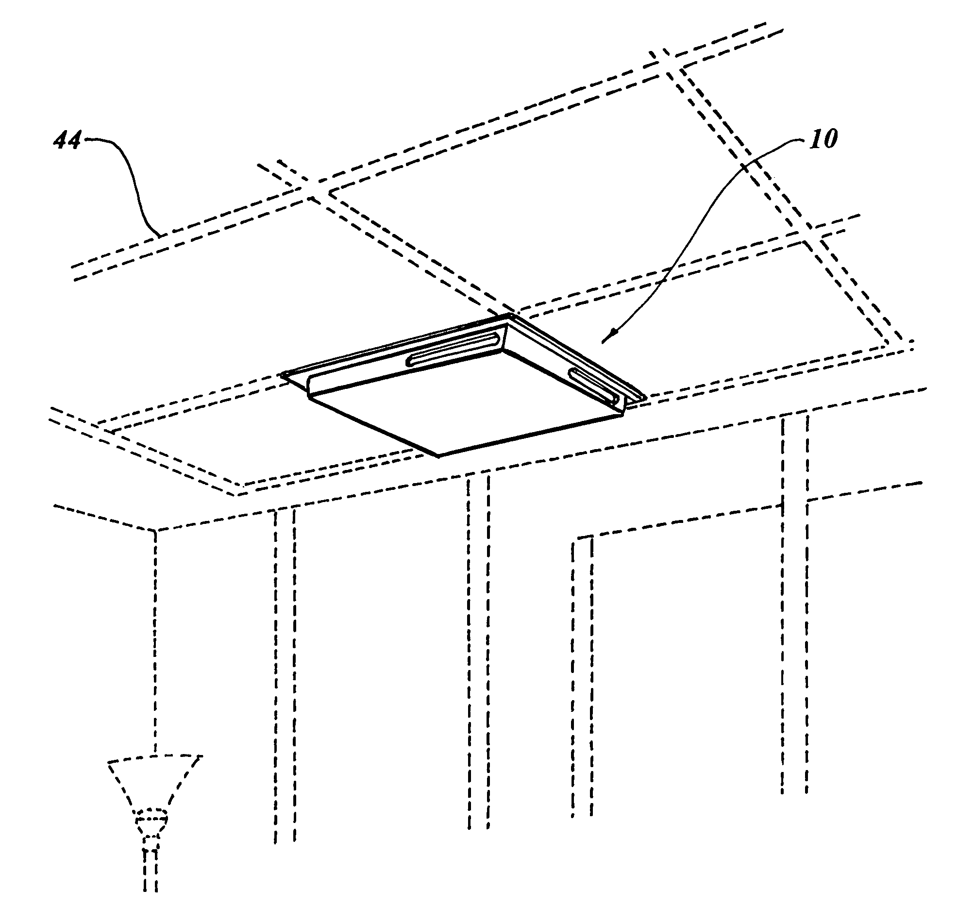
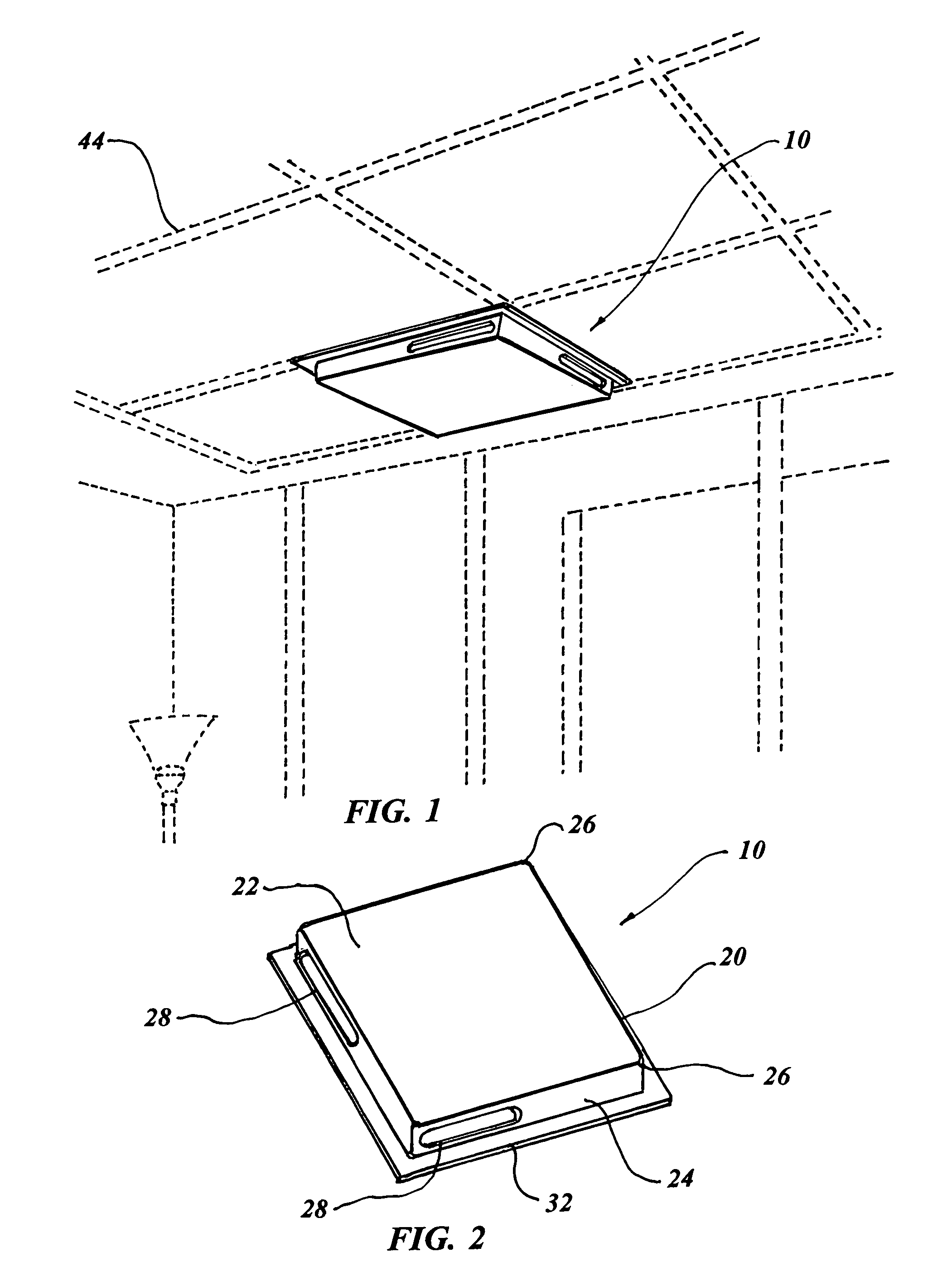
[0082]the invention is for an air vent diverter 48, shown in FIGS. 14-20 and is configured to fit over the top of existing registers, grilles or air diffusers either on a ceiling or a wall of a residential or commercial building. The air vent diverter 48 consists of a diverter body 50 configured to envelop the exposed surface of an existing air vent for a HVAC (heating, ventilating and air conditioning) system.

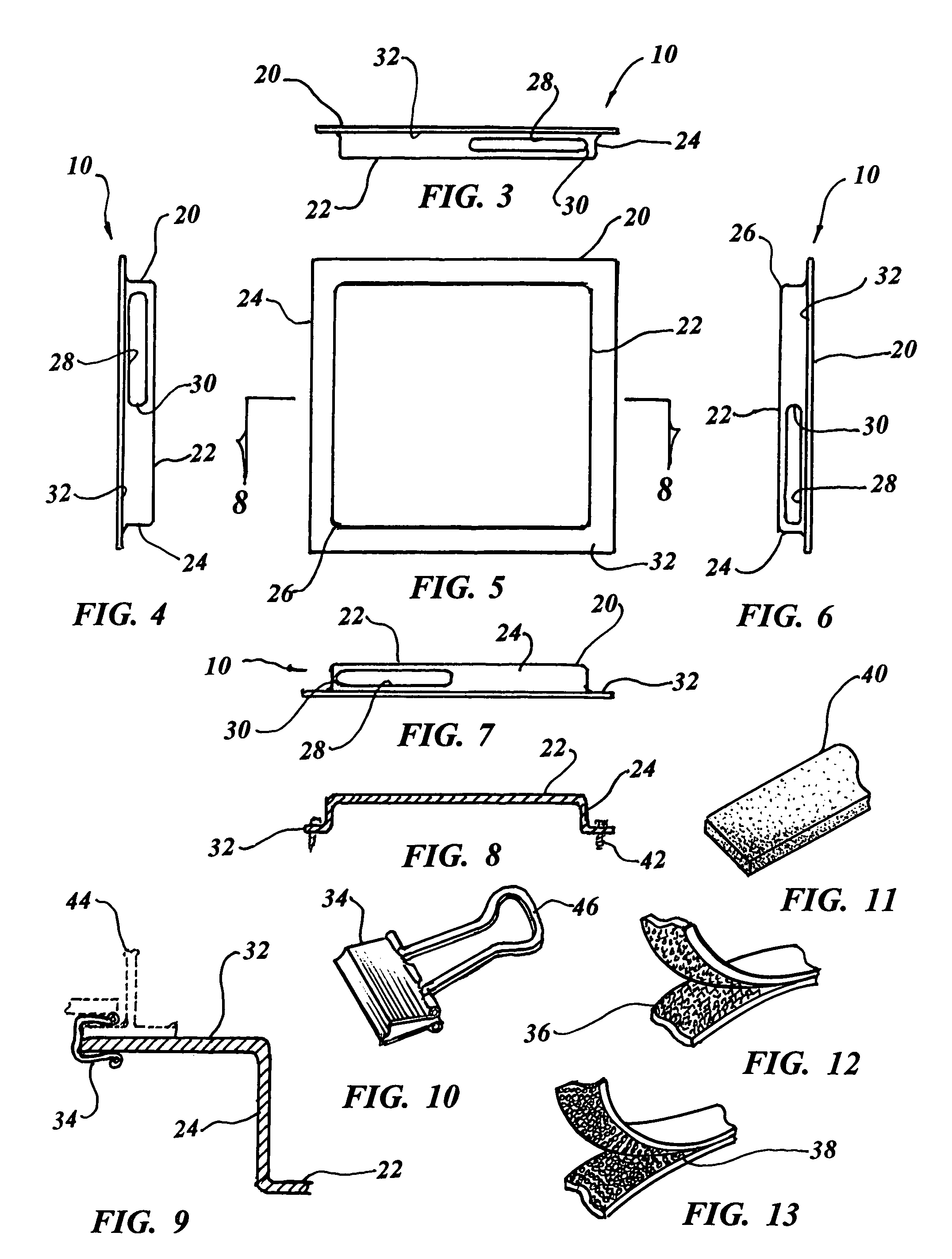
[0083]The air vent diverter body 50 incorporates a flat outside surface 52 with inwardly facing sides 54 and the outside surface 52 has a rectangular configuration with four right angular radial corners 56. Each inwardly facing side 54 has an air discharge slot 58 permitting air to be distributed in opposed directions from the air vent diverter 48. Each discharge air slot 58 contains radial slot ends 30, the same as the preferred embodiment, with the air slots 58 having a width of from 0.9 to 1.10 inch wide (1.0″ nominal) and a length of essentially one half of the diverter 48...

third embodiment

[0087]The third embodiment, illustrated in FIGS. 21-26, discloses a ceiling air duct diverter system 80 comprising a box like housing 82 with side walls 84 having side openings 86 and an open top 88 with the side openings for diverting air flow. An attachment mechanism affixes the open top 88 near a ceiling air vent and consists of fabric hook and loop fasteners, magnets or screws, not illustrated.


PUM


Abstract

A ceiling vent air diverter is taught, in the preferred embodiment, which incorporates a diverter body configured to cover beneath an existing air vent supplying air to a room of a building. The diverter body has a rectangular flat bottom and upstanding sides with each upstanding side having a discharge air slot permitting air to be distributed in opposed directions from the diverter at a ceiling level. A peripheral flange extends outwardly from each side of the body, in parallel relationship with the bottom and is used for attachment to the building ceiling. A second embodiment is configured and functions in the same manner as above but covers over the top of an existing air vent and includes a lip on the underside of the flange. The third embodiment is for a ceiling air duct diverter system consisting of a box like housing with side walls, an open top and open sides to divert air flow and having the capability of affixing the open top near a ceiling air vent.

Description

CROSS REFERENCE TO RELATED APPLICATION[0001]This application is a continuation-in-part of application Ser. No. 11 / 684,858 filed Mar. 12, 2007 now abandoned.FIELD OF THE INVENTION[0002]The present invention is directed toward an air vent diverter which is placed over an existing vent to prevent air from flowing downward and to direct the air across the ceiling to enhance air flow.BACKGROUND OF THE INVENTION[0003]Frequently it is often desirable to divert an air duct in a direction other than that provided by the duct or register. Often the existing duct work may divert the air conditioning / heating in a non-optimized way, such as in a downward direction. This flow direction may introduce cold or hot air toward people causing irritating discomfort particularly in bedrooms where the air may impinge onto sleeping persons.[0004]There have been a number of patents directed to the field of vent covers. U.S. Patent Application Publication No. 20060025067 to Koessler discloses a vent comprisi...

Claims


Application Information

Patent Timeline
Patent Type & Authority Patents(United States)
IPC IPC(8): F24F13/06F24F13/00F24F13/08
CPCF24F13/06F24F2221/14
Inventor PROFETA, JEFFERY L.PECA, MARIO S.GLODERY, GREGORY
Owner PATHSUPPLY INC
Why Eureka
Try Eureka