Implant for correction and stabilization of the spinal column

a technology for spinal columns and implants, applied in joint implants, internal osteosynthesis, medical science, etc., can solve the problems of more degenerative diseases, more stress on adjacent regions of spinal columns, and more degenerative diseases, so as to achieve greater approximation of physiological mobility possibilities

Inactive Publication Date: 2010-01-26
ULRIKH GMBKH & KO KG
View PDF23 Cites 151 Cited by
  • Summary
  • Abstract
  • Description
  • Claims
  • Application Information

AI Technical Summary

Benefits of technology

[0003]The invention is designed to develop an implant so that after its implantation, there is

Problems solved by technology

In the region of the spinal column stiffened by the implant, the natural mobility of healthy vertebra is prohibited, so that adjacent regions of the s

Method used


Image

  • Implant for correction and stabilization of the spinal column
  • Implant for correction and stabilization of the spinal column
  • Implant for correction and stabilization of the spinal column

Examples


Embodiment Construction

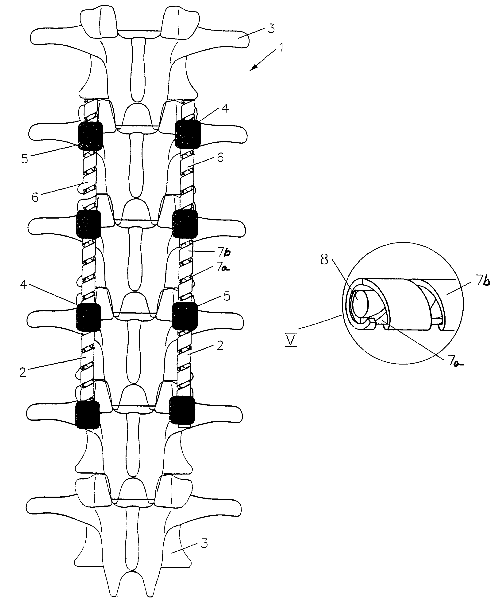
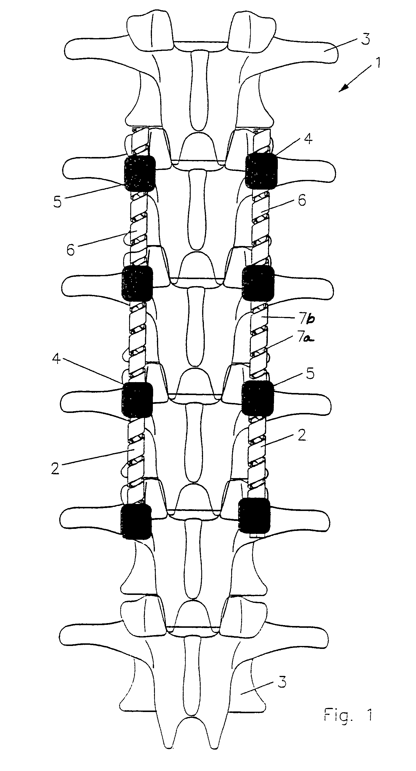
[0025]Referring to the drawings, FIG. 1 shows a spinal column 1, which is supported in its function via two implants 2, which are used to correct and stabilize spinal column 1. These implants 2 help to hold the individual vertebrae 3 of the spinal column 1 in their anatomically correct position. Each implant 2 comprises several pedicle screws 4, as shown in the exemplary embodiment shown, as well as a connection element 6 that connects pedicle screws 4 at their screw heads 5.

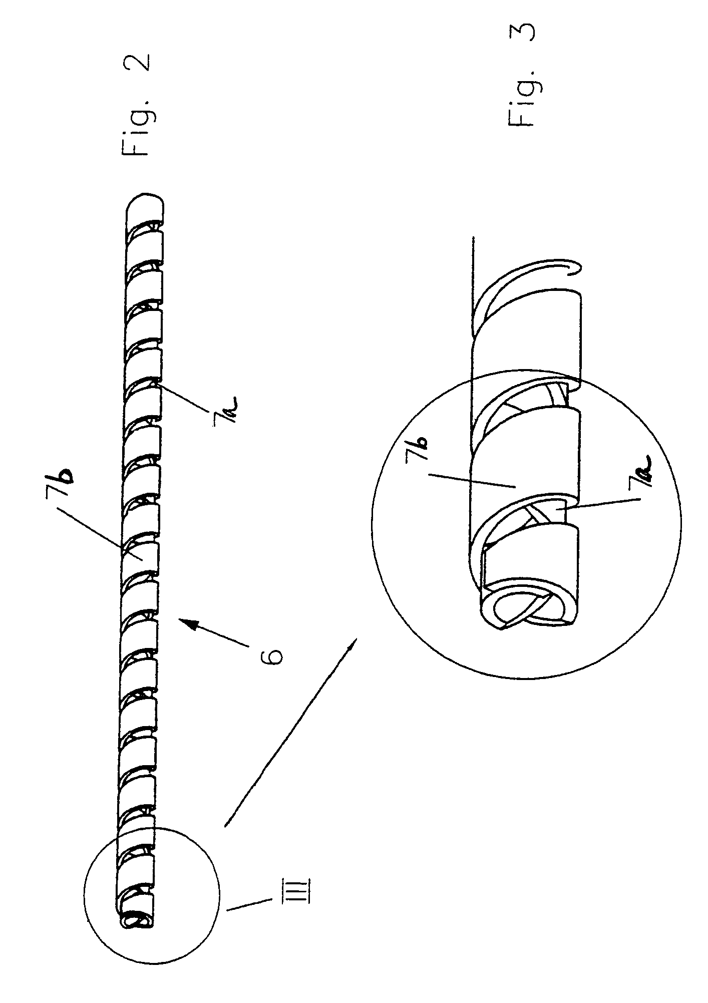
[0026]Connection element 6 is formed by one or more spirals which can include an inner spiral 7a and an outer spiral 7b. The spiral windings of these spirals are arranged offset in the axial direction, following a screw line, whereby adjacent spiral windings have a distance of 0.5 mm to 2.5 mm from one another. FIG. 1 shows an example of a design that relates to the invention, in which a material thickness of 1.2 mm was chosen for the flat wire, from a range of 0.4 mm to 2.8 mm, as well as a material width of 6 ...


PUM


Abstract

An implant for the correction and stabilization of the spinal column, comprising pedicle screws that can be screwed into the vertebrae of a spine, and of at least one connection element that connects the pedicle screws at the screw heads. This connection element is formed by a spiral whose spiral windings are arranged offset in the axial direction, following a screw line.

Description

BACKGROUND OF THE INVENTION[0001]The invention relates to an implant for the correction and stabilization of a spinal column, comprising pedicle screws that can be screwed into the vertebrae, and at least one connection element that connects the pedicle screws at screw heads on the pedicle screws.[0002]Spinal implants are known and described, for example, in German Patent No. DE 41 10 002 C1. In this reference there is an implant, wherein the connection element is formed by a metal rod that is fixed in place on the spinal column, using the pedicle screws. This occurs over the length of at least two adjacent vertebrae, to correct and stabilize the spinal column. This is achieved by pushing the vertebrae into a specific spatial position and fixing or forcing them in place. This act results in a stiffening of the spinal column in a specific region, which guarantees that the spinal column can perform its supporting function, even if individual vertebrae or disks in the intervertebral sp...

Claims


Application Information

Patent Timeline
IPC IPC(8): A61B17/70A61F2/44A61B17/58
CPCA61B17/7028A61B17/7029A61B17/7001Y10S606/907
Inventor MACK, THOMASWILLMANN, NIKOLASSUTCLIFF, JOHNRICHTER, MARCUS
Owner ULRIKH GMBKH & KO KG
Why Eureka
Try Eureka