Magnetic field measuring optically pumped magnetometer apparatus

a technology of optical pumping and magnetic field, which is applied in the direction of optical radiation measurement, instruments, and reradiation, etc., can solve the problems of lowering the accuracy of magnetic field measurement, requiring a long time to bring the cell to a desired temperature, and large periphery of the cell, so as to achieve quick cell bringing and enhance temperature stability

Inactive Publication Date: 2010-01-26
HITACHI HIGH-TECH CORP
View PDF29 Cites 31 Cited by
  • Summary
  • Abstract
  • Description
  • Claims
  • Application Information

AI Technical Summary

Benefits of technology

[0014]The system, in which a transparent film heater is provided to the parts through which irradiation light applied to a cell passes and current is applied to the transparent film heater, thereby retaining the heat of the cell, has an advantage in that the cell is brought to a desired temperature more quickly, compared to the aforementioned heating technique using hot air in a tube. However, the magnetostatic field applied to the cell varies due to the effect of a magnetic field from the heater, lowering the accuracy of magnetic field measurement. Also, there are problems, for example, in that although the cell has been brought to a desired temperature, the fluctuation of the current value becomes large even though current applied to the heater is controlled, because the periphery of the cell is not thermally-insulated.
[0017]The system, in which a film heater is provided to a c-field coil wound on a cavity housing a cell, or a cell, and current is applied to the film heater, thereby retaining the heat of the cell, has advantages in quick response to reach a desired temperature because of the use of a heater, and smaller temperature variations in the cell compared to the aforementioned technique using a heater coil. However, the magnetostatic field applied to the cell varies due to the effect of a magnetic field from the film heater, hindering accurate magnetic field measurement.
[0019]In view of the aforementioned problems, an object of the present invention is to, in a heat retention system for a vapor cell, the cell being a sensor part of an optically pumped magnetometer, quickly bring the cell to a desired temperature, prevent irradiation light passage from being hindered by atoms in the cell adhering to the cell windows through which the irradiation light passes, and acquire data in magnetic measurement taking the effect of a magnetic field from a heater into consideration.
[0020]The present invention uses a cell with their window parts through which irradiation light passes formed of a conductive, temperature-controllable material and with the part of the cell other than the windows formed of a heat-resistant glass. By applying current to the window parts of the cell, the heat of the cell is retained, and by making the windows of the cell have a high temperature, the adherence of atoms to the windows is prevented.
[0024]According to the present invention, since current is applied to conductive, temperature-controllable cell windows provided to irradiation light passing-through parts of a vapor cell, which is a sensor part of an optically pumped magnetometer to directly heat the cell, it is possible to quickly bring the cell to a desired temperature, compared to hot air heating using a conventional hot air generator, and also, since no components such as a hot air inflow tube used in the hot air-used techniques are required, the periphery of the cell can be downsized, and furthermore, adherence of atoms to the laser irradiation light passing-through parts of the cell can be prevented, making it possible to efficiently detect irradiation light. Furthermore, the temperature stability is enhanced because of the consideration of the effect of magnetic fields generated from the cell windows during current is applied. In other words, in the technique according to the present invention, when a desired temperature is reached by means of current application to a conductive glass, the current application is switched on or off in a pulsed manner to suppress the effect of a magnetic field from the conductive glass, and a reference cell is used to correct the magnetic field during current being on in pulsed current application, and the ratio between the S / N ratio and the line width of a magnetooptical resonance signal obtained by application of a RF magnetic field at this time is used to correct the magnetic field detection sensitivity, making consecutive magnetic field measurement possible even in a pulsed current application state.

Problems solved by technology

However, because of heating being performed indirectly, it requires a long time to bring the cell to a desired temperature.
Furthermore, there are problems, for example, in that the periphery of the cell becomes large because thermal insulation is provided to the tube to prevent a temperature decrease.
However, the magnetostatic field applied to the cell varies due to the effect of a magnetic field from the heater, lowering the accuracy of magnetic field measurement.
Also, there are problems, for example, in that although the cell has been brought to a desired temperature, the fluctuation of the current value becomes large even though current applied to the heater is controlled, because the periphery of the cell is not thermally-insulated.
However, irradiation light, which passes through the cell, wavers by the hot air, causing a problem in that the S / N ratio of the irradiation light that has passed through the cell, which is detected when performing magnetic measurement, may greatly deteriorate.
Also, because of the use of hot air, the system becomes large as a result of thermal insulation provided to a hose from the cell to the hot air generator.
The above problems also apply to the system in which hot air is applied using a hot air generator to the inside of a magnetic shielding provided to suppress environmental magnetic noise coming into a cell to fill the magnetic shielding with hot air, thereby retaining the heat of the cell.
However, when using the coil as a heater, an accurate temperature cannot be obtained by measuring the outer side of the coil because a temperature increase in a coil exhibits a fairly large temperature gradient from the inner portion toward the outer portion.
Also, a part of the cavity is heated using a heat transistor after the current applied to the heater coil is turned off, causing problems, for example, in that temperature variations occurs in the cell.

Method used


Image

  • Magnetic field measuring optically pumped magnetometer apparatus
  • Magnetic field measuring optically pumped magnetometer apparatus
  • Magnetic field measuring optically pumped magnetometer apparatus

Examples


example 1

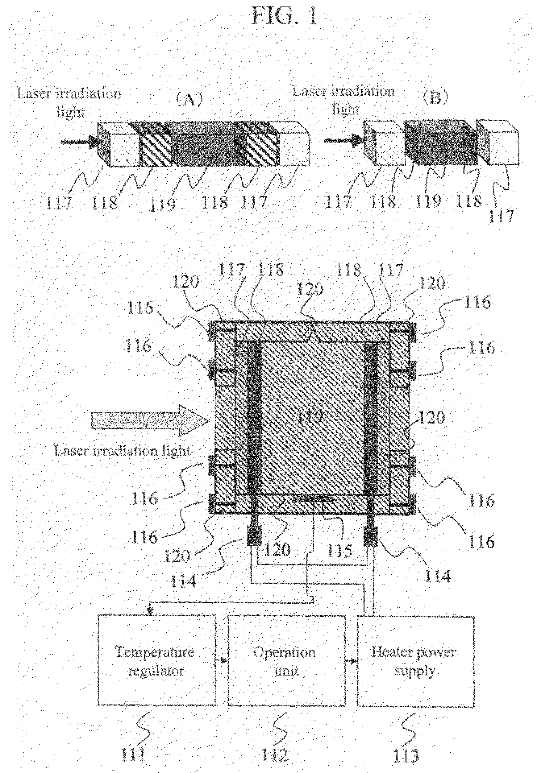
[0067]Example 1 of the present invention will be described using FIG. 1.

[0068]First, as an example of FIG. 1(A), the transparent film heaters 118 are provided to the laser irradiation light passing-through parts of the vapor cell 119, and current is applied to the transparent film heaters 118, thereby retaining the heat of the vapor cell 119. It is preferable that the vapor cell 119 and the transparent film heaters 118 are not bonded with an adhesive, etc., so that they can be replaced when they are deteriorated.

[0069]Also, in order to prevent a heat retention efficiency decrease caused as a result of the transparent film heaters 118 or the cell windows of the vapor cell using the conductive glass (ITO) shown in FIG. 1(B) being directly exposed to external air, the heat-resistant glasses 117 are required for the laser irradiation light passing-through parts of the vapor cell 119, and the transparent film heaters 118 are required between the heat-resistant glasses 117 and the vapor c...

example 2

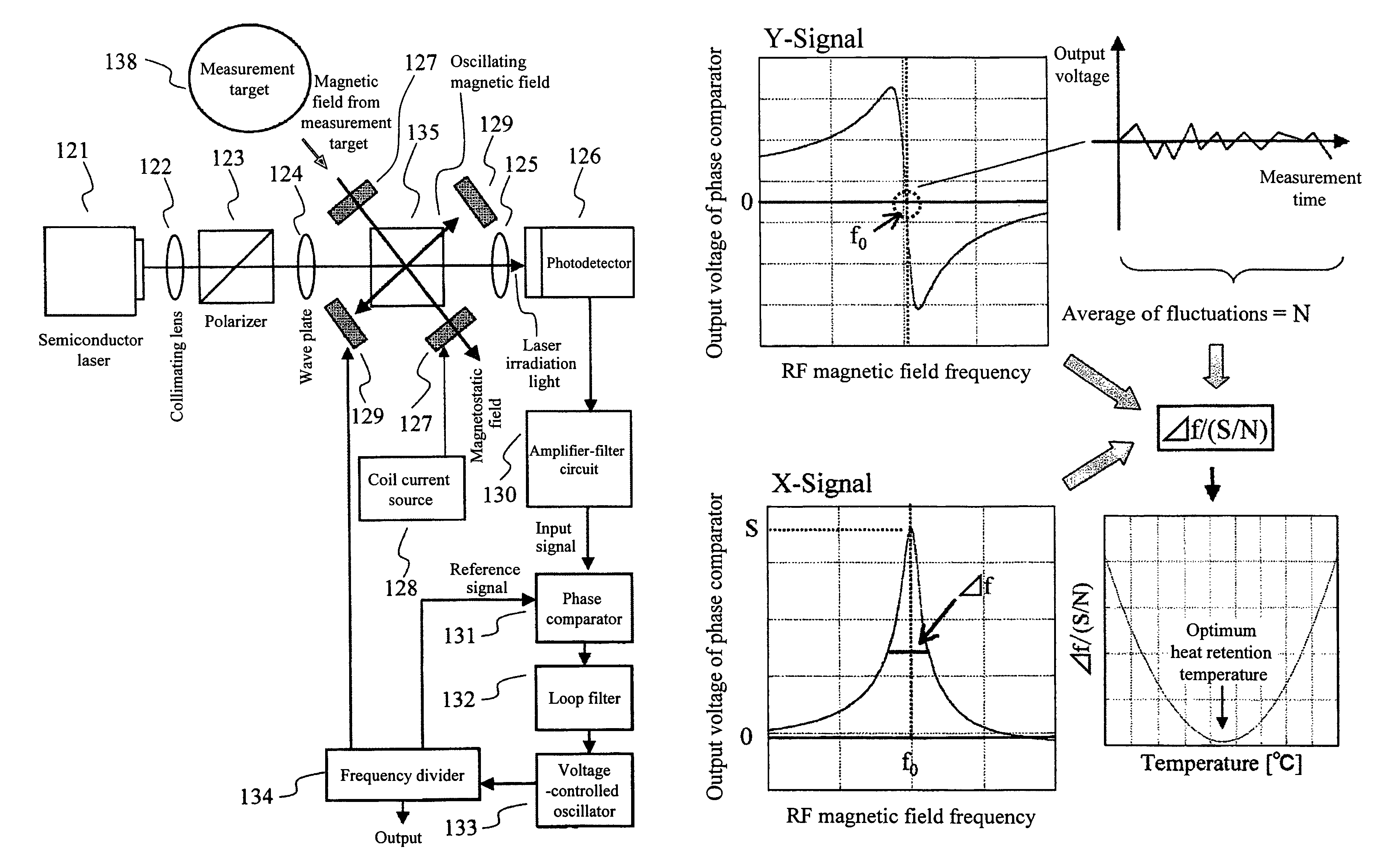
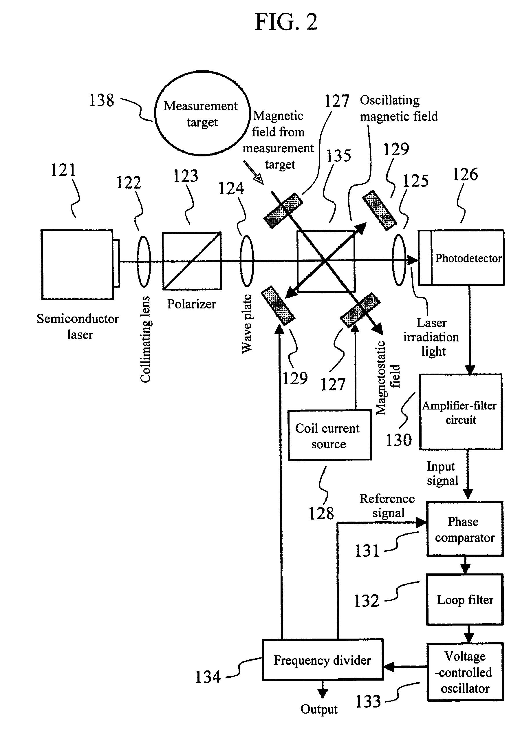
[0071]Example 2 of the present invention will be describe using FIG. 2. FIG. 2 shows an optically pumped magnetometer requiring a vapor cell heat retention system 135 according to the present invention, the system being a heat retention sensor part including a vapor cell heated by the transparent film heaters 118 shown in FIG. 1. Using the vapor cell heat retention system 135, the vapor cell 119 is heated to a desired temperature. Laser irradiation light from the semiconductor laser 121 is converted into circularly-polarized light via the collimating lens 122, the polarizer 123 and the wave plate 124, and the circularly-polarized light is irradiated to the vapor cell 119 to which a magnetostatic field is applied by the magnetostatic field application coils 127. At this time, a RF magnetic field is applied from the RF coils 129 in a direction perpendicular to the magnetostatic field application direction, and the laser irradiation light modulated by the RF magnetic field is detected ...

example 3

[0073]Example 3 of the present invention will be described using FIG. 4. As shown in FIG. 3, two vapor cell heat retention systems are required; one is used for a magnetic field measurement sensor, and the other is used for a reference sensor for determining the effect of current applied to the transparent film heaters 118.

[0074]Laser irradiation light from the semiconductor laser 121 is made to be parallel light by the collimating lens 122, and the laser irradiation light is split into two by means of a beam splitter 137 after it is converted into circularly-polarized light via the polarizer 123 and the wave plate 124. One of the laser irradiation light split into two is applied to the vapor cell 119 for the magnetic field measurement sensor, and the other is applied to the vapor cell heat retention system 135 including the vapor cell 119 for the reference sensor. Each vapor cell has the magnetostatic field application coils 127, and a magnetostatic field of the same strength is ap...


PUM


Abstract

Providing: quickly brining a vapor cell 119 to a desired temperature when retaining the heat of the vapor cell 119 to enhance the magnetic field detection performance of an optically pumped magnetometer; preventing adherence of atoms in the vapor cell 119 to a laser irradiation light passing-through part of the vapor cell 119; downsizing the periphery of the vapor cell 119; and suppressing the effect of a magnetic field from a heater used to retain the heat of the vapor cell 119. The present invention includes: a transparent film heater 118 provided to a laser irradiation light passing-through part of a vapor cell 119, the vapor cell 119 being a magnetic detection part of the optically pumped magnetometer; a temperature detector 115 provided at a center part of a side of the vapor cell 119; a temperature regulator 111 that sets a desired temperature for heat retention of the vapor cell 119 and compares the desired temperature and the actual temperature of the vapor cell measured by the temperature detector 115; an operation unit 112 that upon receipt of a PID control signal for temperature control from the temperature regulator 111, performs a temperature adjustment and switches on / off, in a pulsed manner, current applied to the transparent film heater 118 after the desired temperature is reached; and a heater power supply 113 that upon receipt of an operation signal from the operation unit 112, applies current to the transparent film heater 118.

Description

CLAIM OF PRIORITY[0001]The present application claims priority from Japanese application JP 2007-168373 filed on Jun. 27, 2007, the content of which is hereby incorporated by reference into this application.BACKGROUND OF THE INVENTION[0002]1. Field of the Invention[0003]The present invention relates to a technique for retaining the heat of a sensor part of an optically pumped magnetometer.[0004]2. Background Art[0005]In order to increase alkali metal atoms in a vapor cell which are excited by irradiation light applied to the cell, it is necessary to increase the gas density of the alkali metal in the cell by heating the cell. In order to retain the heat of the cell, there are techniques using hot air or heaters.[0006]Appl. Phys. B76, 325-328 (2003) discloses that a cell is housed in a plastic coiled tube and the heat of the cell is retained by applying hot air to the inside of the tube using a hot air generator.[0007]APPLIED PHYSICS LETTERS 85, 6409 (2004) discloses that transparent...

Claims


Application Information

Patent Timeline
Patent Type & Authority Patents(United States)
IPC IPC(8): G01V3/00G01R33/032H03L7/26
CPCG01R33/26G01R33/032
Inventor KAWABATA, RYUZOU
Owner HITACHI HIGH-TECH CORP
Why Eureka
Try Eureka