
Tappet clearance adjustment device

a technology of adjustment device and tappet, which is applied in the direction of mechanical equipment, machines/engines, manufacturing tools, etc., can solve the problems of complex procedure for operating robots, inability to adjust screws at the appropriate direction, and inability to adjust screws smoothly. the effect of rotating the adjustment screw

Inactive Publication Date: 2010-02-02
HONDA MOTOR CO LTD
View PDF19 Cites 2 Cited by
  • Summary
  • Abstract
  • Description
  • Claims
  • Application Information

AI Technical Summary

Benefits of technology

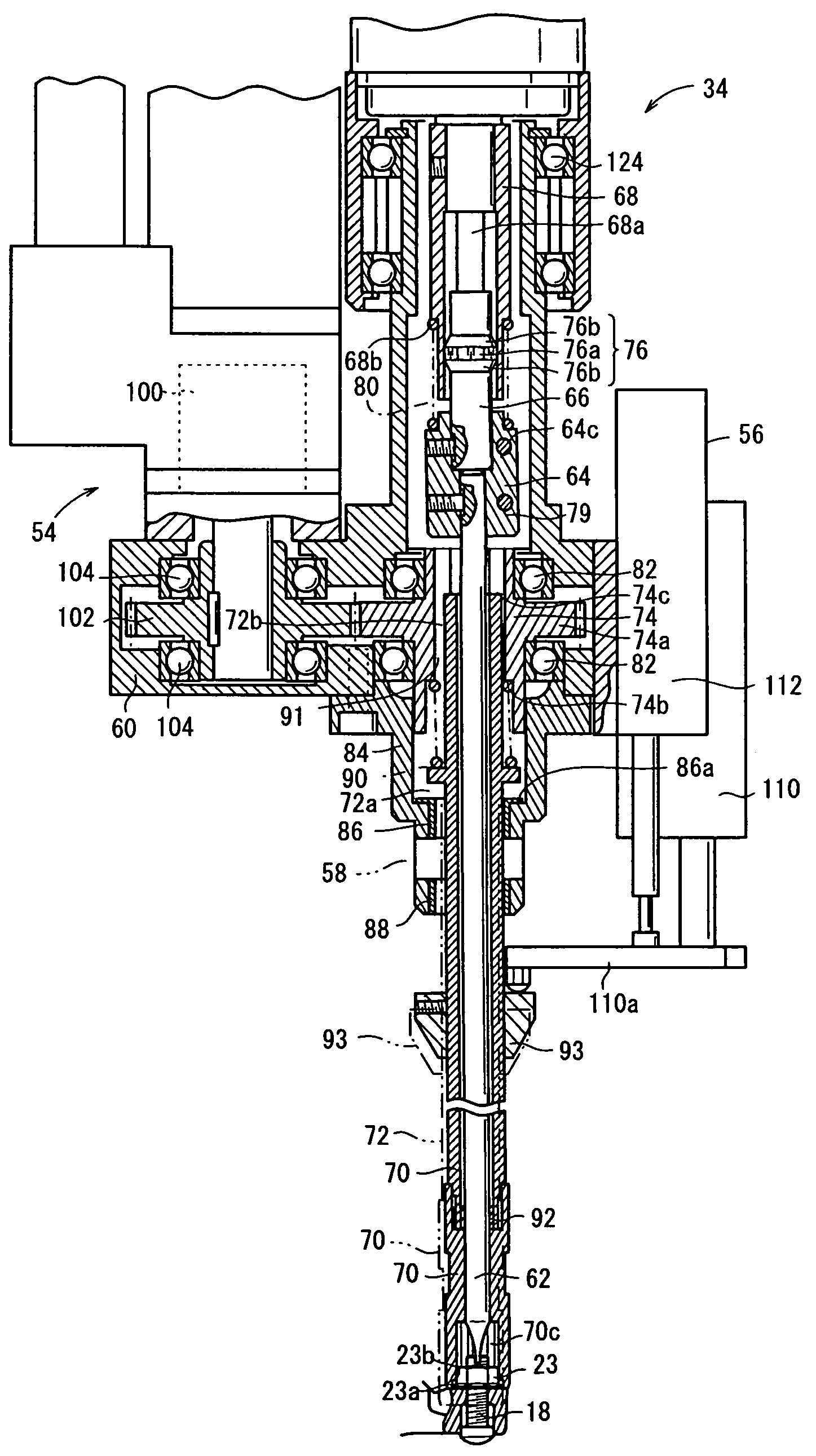
The present invention provides a tappet clearance adjusting apparatus that can smoothly engage and disengage an adjustment screw and an adjustment nut in an engine. The apparatus includes a screwdriver, a first rotational driver, a sleeve, a second rotational driver, a pipe, and a torque sensor. The screwdriver is connected to the adjustment screw through a rotational engagement, and the socket is fitted over the adjustment nut. The apparatus allows for tilting movement, sliding movement, and rotation of the adjustment screw and the adjustment nut, ensuring proper alignment and engagement. The apparatus provides a reliable and accurate method for adjusting the clearance between the adjustment screw and the valve end of the engine.

Problems solved by technology

If the tappet clearance is too large, then the valve end and the adjustment screw produce large sounds as noise upon contact with each other.
However, since the angle of the adjustment screw varies depending on the amount of lift of the valve, a procedure for operating the robot becomes complex, in order to cause the robot to respond to changes in the angle of the adjustment screw.
The adjustment screw may not necessarily be set at an appropriate direction, due to slight operational delays of the robot or the like.
However, the fastening device disclosed in Japanese Laid-Open Patent Publication No. 6-39655 includes a rotary mechanism at a bent tip portion thereof, which is too complex to rotate smoothly for detecting rotational torque with high accuracy.
Even if the fastening device is able to hold the screwdriver in engagement with the adjustment screw and at an appropriate direction, the fastening device cannot be used to adjust the tappet clearance, since it is devoid of any mechanism for rotating the adjustment nut.

Method used


Image

  • Tappet clearance adjustment device
  • Tappet clearance adjustment device
  • Tappet clearance adjustment device

Examples


Embodiment Construction

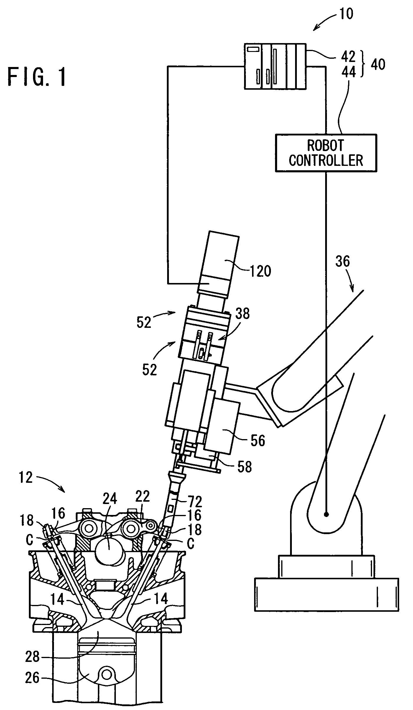
[0033]A tappet clearance adjusting apparatus according to an embodiment of the present invention shall be described below with reference to FIGS. 1 through 13 of the accompanying drawings.

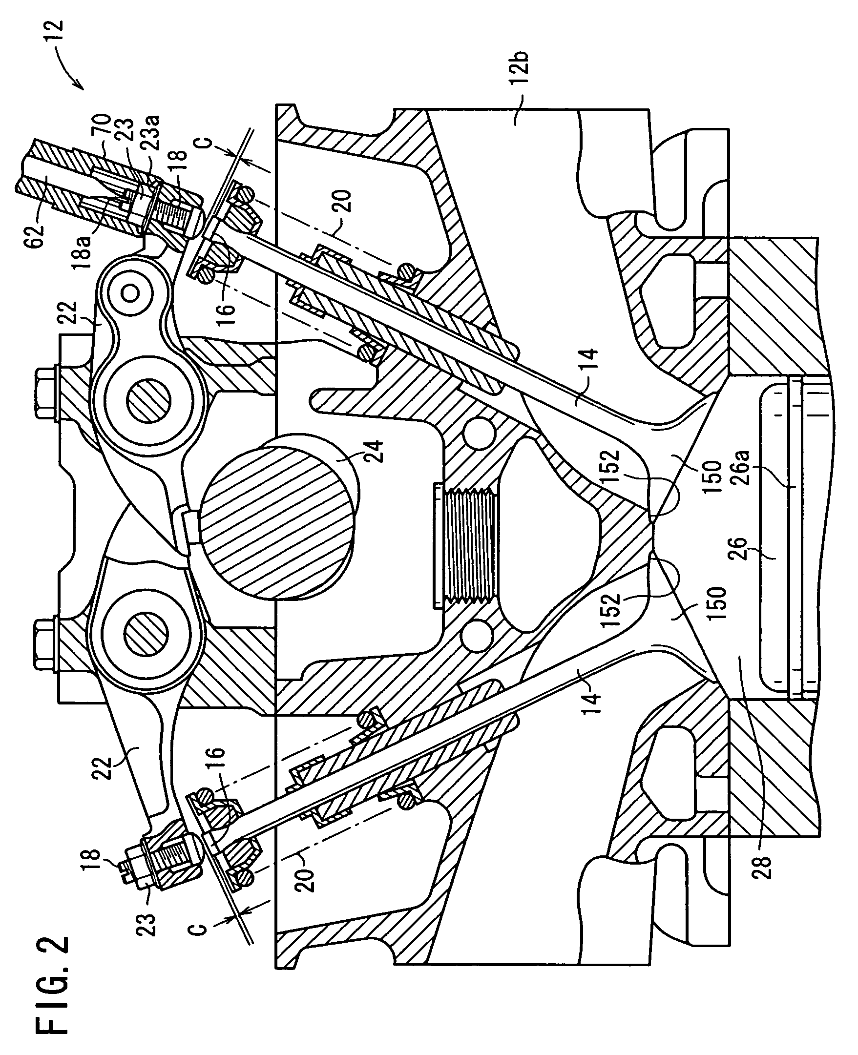
[0034]As shown in FIG. 1, a tappet clearance adjusting apparatus 10 according to an embodiment of the present invention constitutes an apparatus for adjusting a clearance (hereinafter referred to as a tappet clearance) C between a valve end 16 of a valve 14 of an engine 12 and an adjustment screw 18. The adjustment screw 18 is a fine right-handed screw, which is advanced downwardly when it is rotated clockwise.

[0035]As shown in FIG. 2, the adjustment screw 18 includes a screw section having a straight slot 18a defined in an upper end thereof, the screw section being threaded into the distal end of a rocker arm 22. The adjustment screw 18 is fixed in place by an adjustment nut 23, in a double-nut configuration. The adjustment nut 23 comprises a nut having a flange 23a thereon (e.g., a nut according ...


PUM


Abstract

An adjustment unit has a driver for turning an adjustment screw, a sleeve having a hexagonal hole connected to a rotating shaft, an insertion member connected to the upper end of the driver and of which a part is inserted in the sleeve, a pipe concentrically provided around the driver and having at its forward end a socket for rotating an adjustment nut, and a gear body provided concentric with the pipe and rotating the pipe. The sleeve has a short tiltable support section in contact with the hexagonal hole. A gap is provided between the hexagonal hole of the gear body and a hexagonal column section of the pipe. The driver and the pipe tilt about the tilting support section as the fulcrum.

Description

CROSS-REFERENCE TO RELATED APPLICATIONS[0001]The present application is a U.S. National phase of, and claims priority based on PCT / JP2006 / 309961, filed 18 May 2006, which, in turn, claims priority from Japanese patent application 2005-189021, filed 28 Jun. 2005. The entire disclosure of each of the referenced priority documents is incorporated herein by reference.TECHNICAL FIELD[0002]The present invention relates to a tappet clearance adjusting apparatus (device) for adjusting a clearance between a valve and an adjustment screw in an engine, in which a valve that is closed by a spring is opened by being pressed by an adjustment screw on a distal end of a rocker arm.BACKGROUND ART[0003]Engines of the type having a rocker arm in a valve mechanism draw in and discharge a fuel gas or an exhaust gas by pressing a valve end to open the valve with an adjustment screw on the distal end of a rocker arm that is actuated by a cam. When the rocker arm returns to its original position, the valve...

Claims


Application Information

Patent Timeline
Patent Type & Authority Patents(United States)
IPC IPC(8): B25B13/48B25B21/00
CPCF01L1/20F01L1/181F01L2103/01F01L2303/01B23P19/06F01L1/46
Inventor TACHINO, YASUYUKIMIYAJIMA, TOSHIYUKITSUYOSHI, TOMOAKI
Owner HONDA MOTOR CO LTD
Learn More