Engine piston having an insulating air gap

a technology of insulating air gap and engine, which is applied in the direction of trunk pistons, cylinders, plungers, etc., can solve the problems of increasing damaging the piston, and not fully utilizing the insulating air gap to reduce heat extraction from the combustion chamber

Active Publication Date: 2010-02-02
CATERPILLAR INC
View PDF27 Cites 21 Cited by
  • Summary
  • Abstract
  • Description
  • Claims
  • Application Information

AI Technical Summary

Problems solved by technology

While the heat of combustion is necessary to generate power, it can also damage the piston.
Cooling the piston, however, increases heat extraction from the combustion chamber through the piston.
Although the piston of the '494 patent may reduce heat extraction from the piston by providing an air gap on the side walls of the combustion bowl, it does not fully utilize an insulating air gap to reduce heat extraction from the combustion chamber.
Since the bulk of the piston main body is passively cooled by the natural breathing action set up by expansion and contraction of gases within the central cavity, the piston of the '494 patent may be inadequately cooled.
Also, attaching the insert to the piston main body using retention clips may increase the likelihood of the insert separating from the piston body due to inertia, during reciprocating motion of the piston.

Method used


Image

  • Engine piston having an insulating air gap
  • Engine piston having an insulating air gap
  • Engine piston having an insulating air gap

Examples


Embodiment Construction

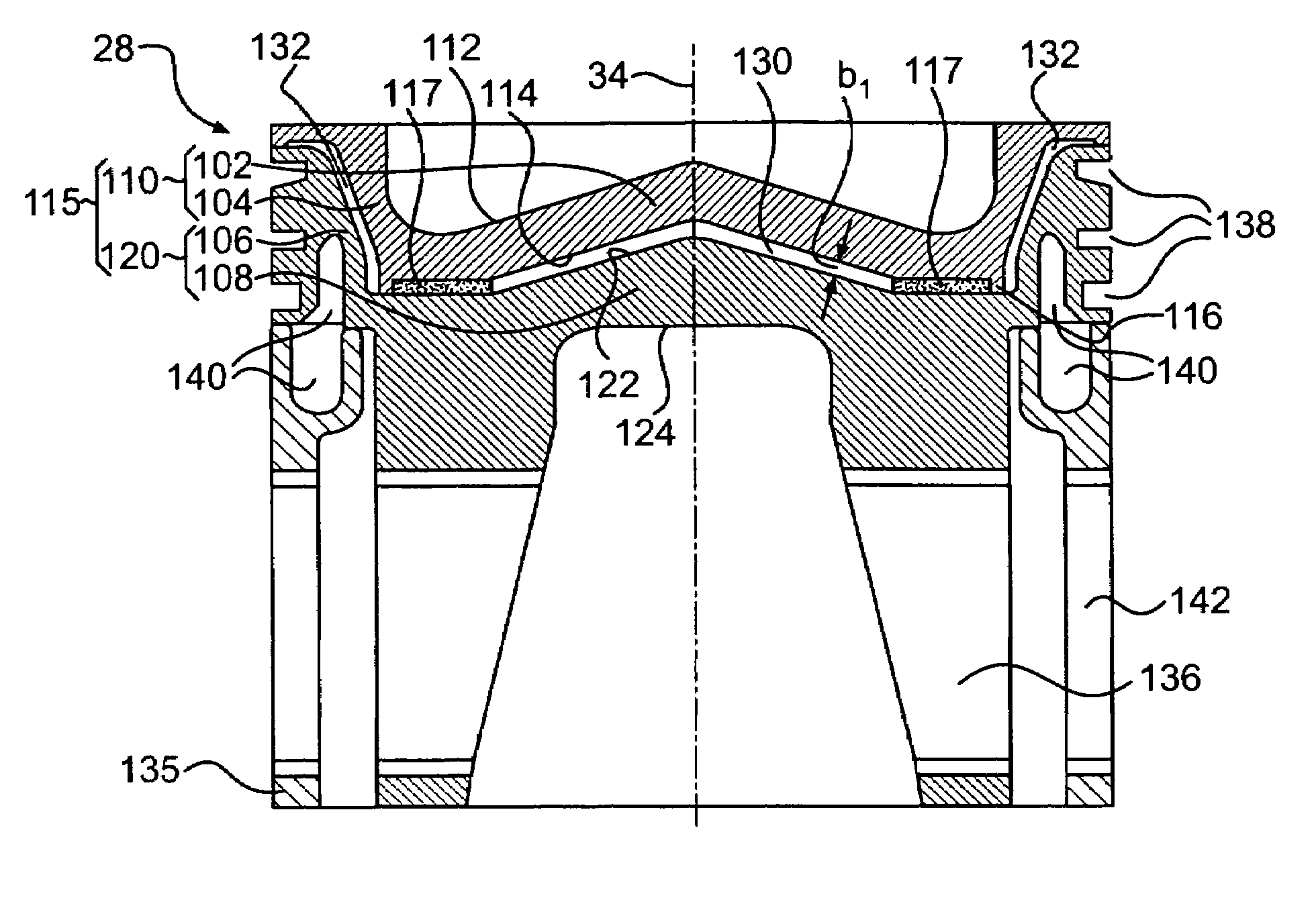
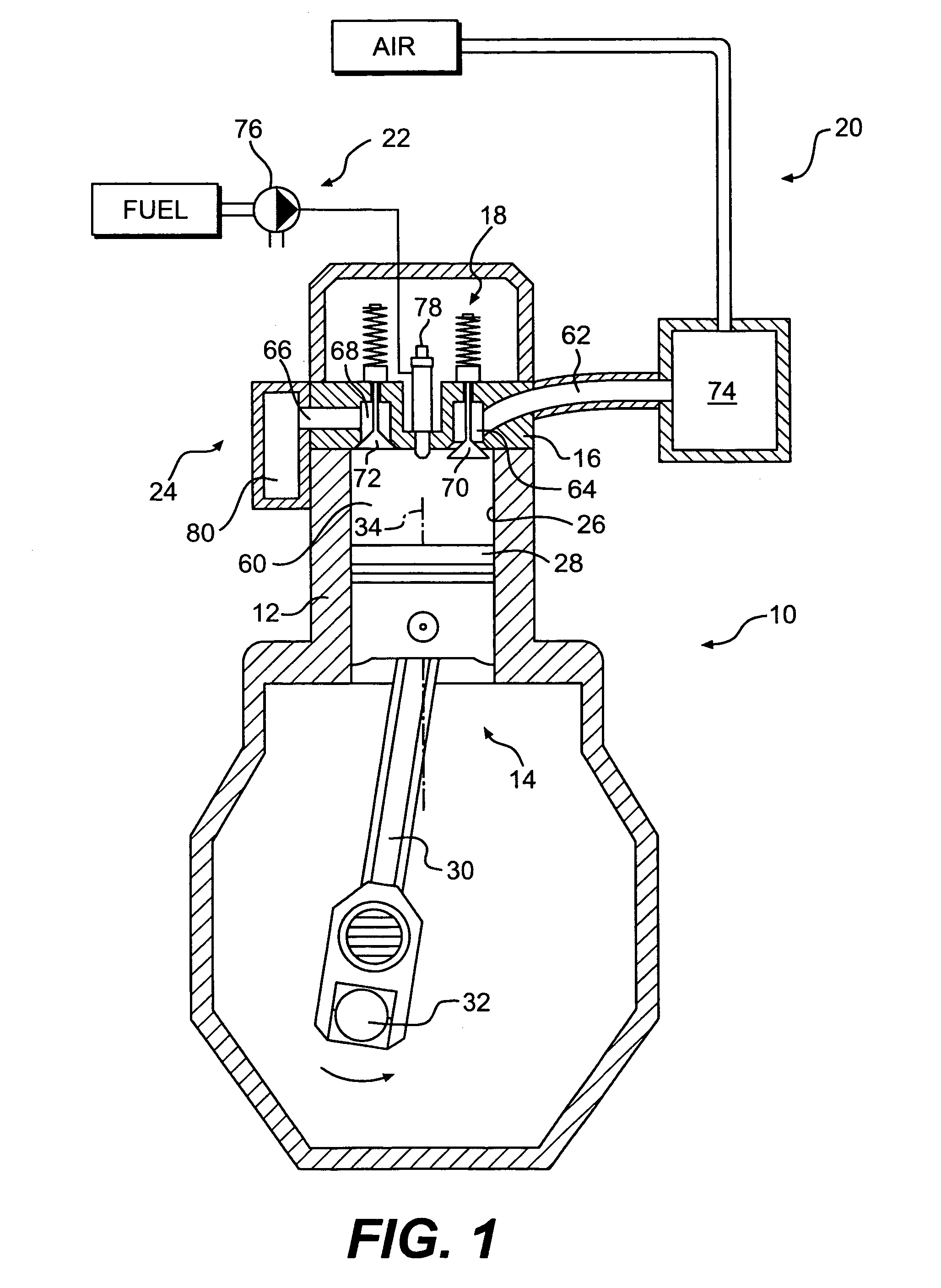
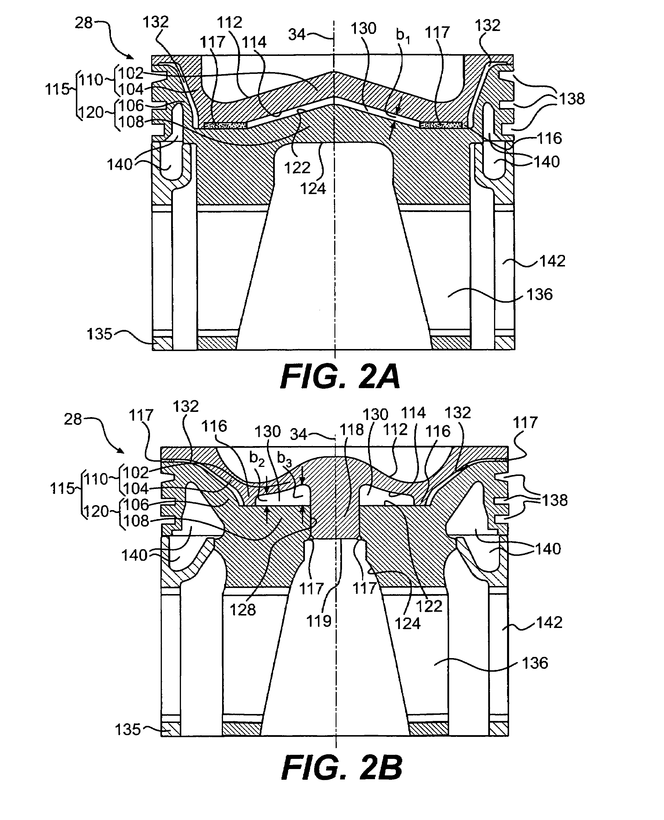
[0016]An exemplary internal combustion engine (engine) 10 is illustrated in FIG. 1. Engine 10 is depicted and described as a 4-stroke diesel engine. However, it is contemplated that engine 10 may be any other type of engine, such as, for example, a 2-stroke diesel engine, a gasoline engine, or natural gas engine. Engine 10 may include an engine block 12, one or more piston assemblies 14, a cylinder head 16 associated with each piston assembly 14, a valve actuation system 18, an air induction system 20, a fuel system 22, and an exhaust system 24. Although the engine 10 is depicted as having one cylinder 26, engine 10 can have any number of cylinders 26.

[0017]Engine block 12 may be a central structural member defining a plurality of cylinders 26 (only one shown). One of piston assemblies 14 may be slidably disposed within each of cylinders 26. It is contemplated that the cylinders 26 may be disposed in an “in-line” configuration, a “V” configuration, or any other conventional configur...


PUM


Abstract

A piston for an internal combustion engine has an upper crown with a top and a bottom surface, and a lower crown with a top and a bottom surface. The upper crown and the lower crown are fixedly attached to each other using welds, with the bottom surface of the upper crown and the top surface of the lower crown forming a mating surface. The piston also has at least one centrally located air gap formed on the mating surface. The air gap is sealed to prevent substantial airflow into or out of the air gap.

Description

U.S. GOVERNMENT RIGHTS[0001]This invention was made with government support under the terms of Contract No. DE-FC05-00OR22806 awarded by the Department of Energy. The government may have certain rights in this invention.TECHNICAL FIELD[0002]The present disclosure relates generally to a piston for an engine and, more particularly, to an engine piston having an insulating air gap.BACKGROUND[0003]Internal combustion engines, including diesel engines, gasoline engines, natural gas engines, and other engines known in the art, operate by converting heat energy of fuels to kinetic energy. In an internal combustion engine, burning of a fuel occurs in a confined space called a combustion chamber. This burning of fuel creates gases of high temperature and pressure, which expand to cause movement, for example by acting on one or more pistons. To increase efficiency of these engines it is useful to convert as much of the heat of combustion to useful work as possible, by reducing the amount of h...

Claims


Application Information

Patent Timeline
Patent Type & Authority Patents(United States)
IPC IPC(8): F02F3/00
CPCF02F3/0023F02F3/003F16J1/006F02F3/26F02F2003/0061
Inventor JARRETT, MARK WAYNEHUNOLD, BRENT MICHAEL
Owner CATERPILLAR INC
Why Eureka
Try Eureka