
Electro-optical device and electronic apparatus
a technology of optical devices and electronic devices, applied in piezoelectric/electrostrictive transducers, identification means, instruments, etc., can solve the problems of inability to achieve satisfactory reduction in inability to increase enclosure thickness, and inability to increase the size or thickness of enclosures
- Summary
- Abstract
- Description
- Claims
- Application Information
AI Technical Summary
Benefits of technology
Problems solved by technology
Method used
Image

Examples
first embodiment
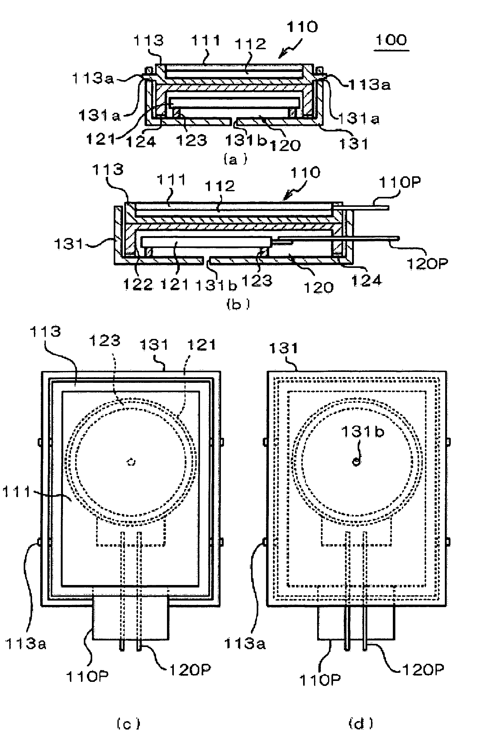
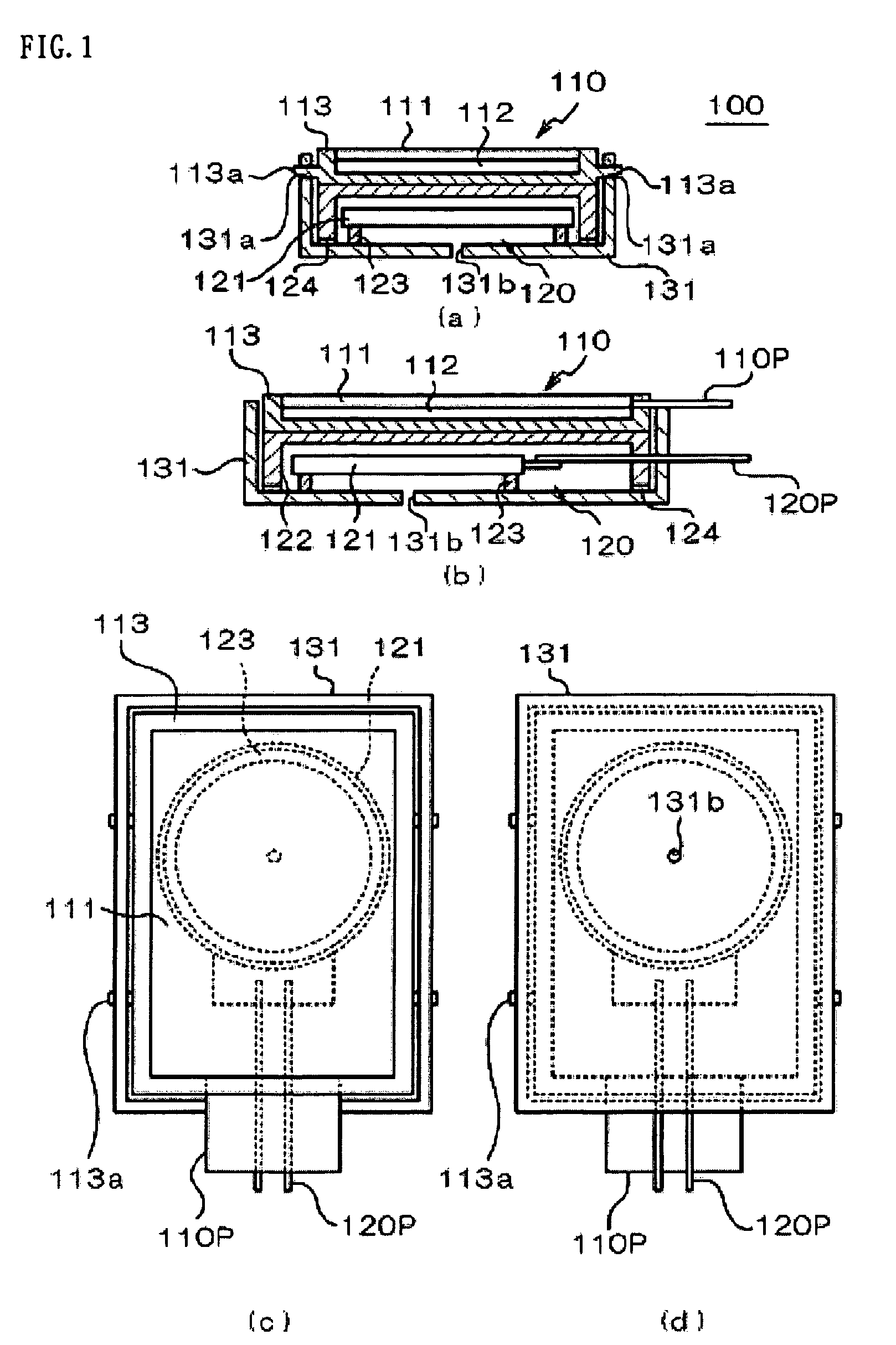
[0039]FIG. 1A shows a cross-sectional view showing a cross section taken along one direction (direction of the shorter side); FIG. 1B shows a cross-sectional view showing a cross section taken along the other direction (direction of the longer side); FIG. 1C shows a plan view; and FIG. 1D shows a bottom view of the electro-optical device with a sound generating body 100 according to the present invention. FIG. 4A is a side view of the electro-optical device with a sound generating body 100. The electro-optical device with a sound generating body 100 includes a display unit 110 provided with an electro-optical panel 111 and a sound generating unit 120 provided with a sound generating body 121.
[0040]The electro-optical panel 111 may be formed of various electro-optical devices such as a liquid crystal display panel, an organic electroluminescence panel, a plasma display panel, or a field emission panel. However, in this specification, it is basically assumed to be a liquid crystal dis...
second embodiment
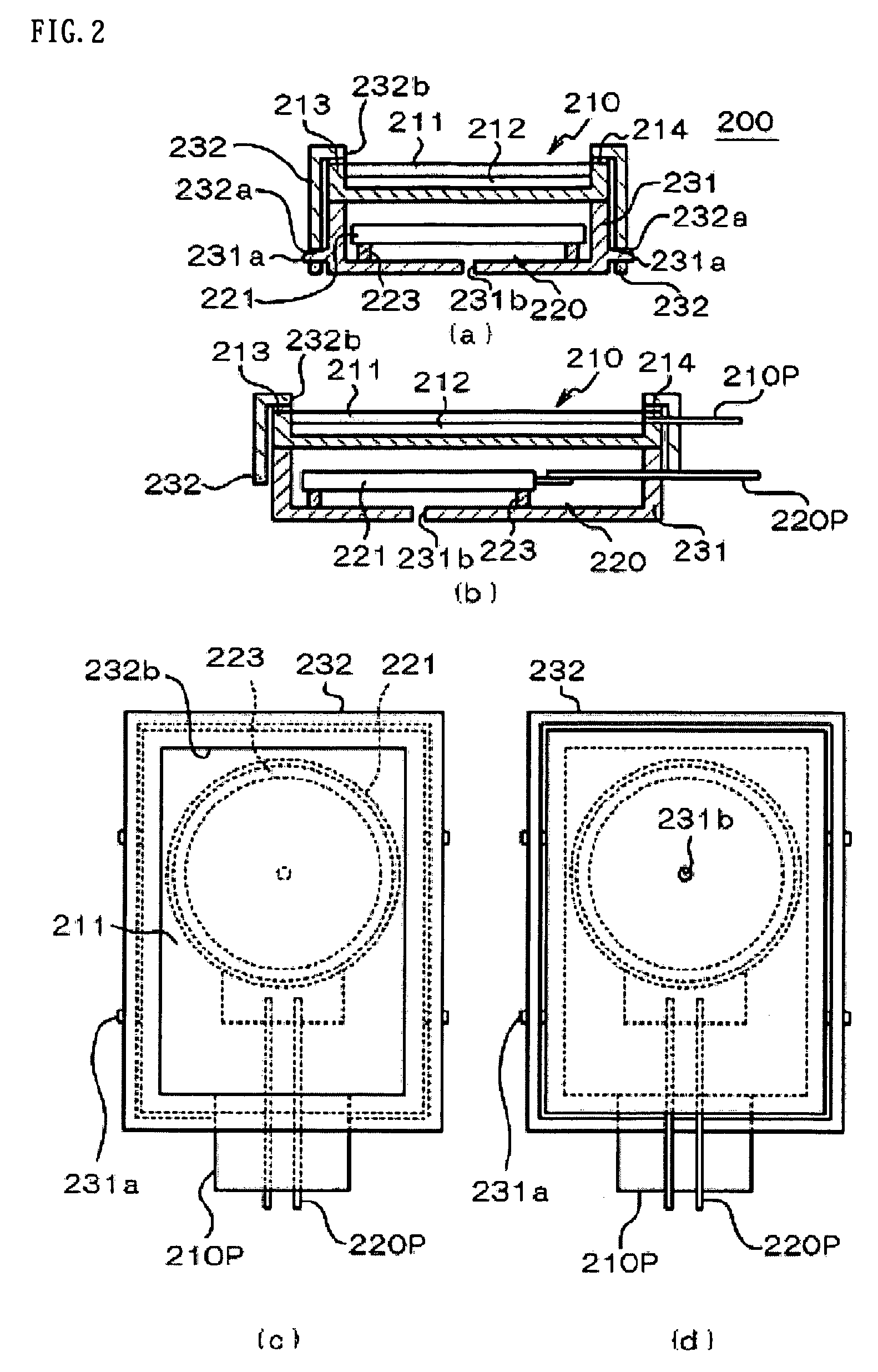
[0061]Referring now to FIGS. 2A to 2D, a second embodiment of the present invention will be described. FIG. 2A shows a cross-sectional view showing a cross section along one direction (direction of the shorter side) of an electro-optical device 200 with a sound generating body of the second embodiment; FIG. 2B shows a cross-sectional view showing a cross section along another direction (direction of the longer side); FIG. 2C shows a plan view; and FIG. 2D shows a bottom view. FIG. 4B is a side view of the electro-optical device 200 with a sound generating body.
[0062]The electro-optical device 200 with a sound generating body includes a display unit 210 provided with an electro-optical panel 211, and a sound generating unit 220 provided with a sound generating body 221. Since the electro-optical panel 211, a back light 212, a panel holding frame 213, the sound generating body 221, a supporting member 223, wiring members 210P, and 220P are the same as those in the first embodiment, de...
third embodiment
[0066]Referring now to FIGS. 3A to 3D, a third embodiment of the present invention will be described. FIG. 3A shows a cross-sectional view showing a cross section taken along one direction (direction of the shorter side) of an electro-optical device 300 with a sound generating body of the third embodiment; FIG. 3B shows a cross-sectional view showing a cross section taken along another direction (direction of the longer side); FIG. 3C shows a plan view and FIG. 3D shows a bottom view. FIG. 4C is a side view of the electro-optical device 300 with a sound generating body.
[0067]In the electro-optical device 300 with a sound generating body according to this embodiment includes a display unit 310 provided with an electro-optical panel 311 and a sound generating unit 320 provided with a sound generating body 321. The electro-optical panel 311, a backlight 312, a panel holding frame 313, the sound generating body 321, a sound generating frame 322, a supporting member 323, a shock absorbin...
PUM
| Property | Measurement | Unit |
|---|---|---|
| thickness | aaaaa | aaaaa |
| size | aaaaa | aaaaa |
| rigidity | aaaaa | aaaaa |
Abstract
Description
Claims
Application Information