RF transceiver front-end

a transceiver and front-end technology, applied in the field of wireless communication systems, can solve the problems of signal strength variation, rf signals typically experience multiple path fading,

Inactive Publication Date: 2010-02-02
AVAGO TECH WIRELESS IP SINGAPORE PTE
View PDF6 Cites 13 Cited by
  • Summary
  • Abstract
  • Description
  • Claims
  • Application Information

AI Technical Summary

Problems solved by technology

In addition, RF signals typically experience multiple path fading (i.e., transmission of an RF signal to a receiver occurs over multiple paths that are of different lengths causing the signal strength to vary with minor changes in position).

Method used


Image

  • RF transceiver front-end
  • RF transceiver front-end
  • RF transceiver front-end

Examples


Embodiment Construction

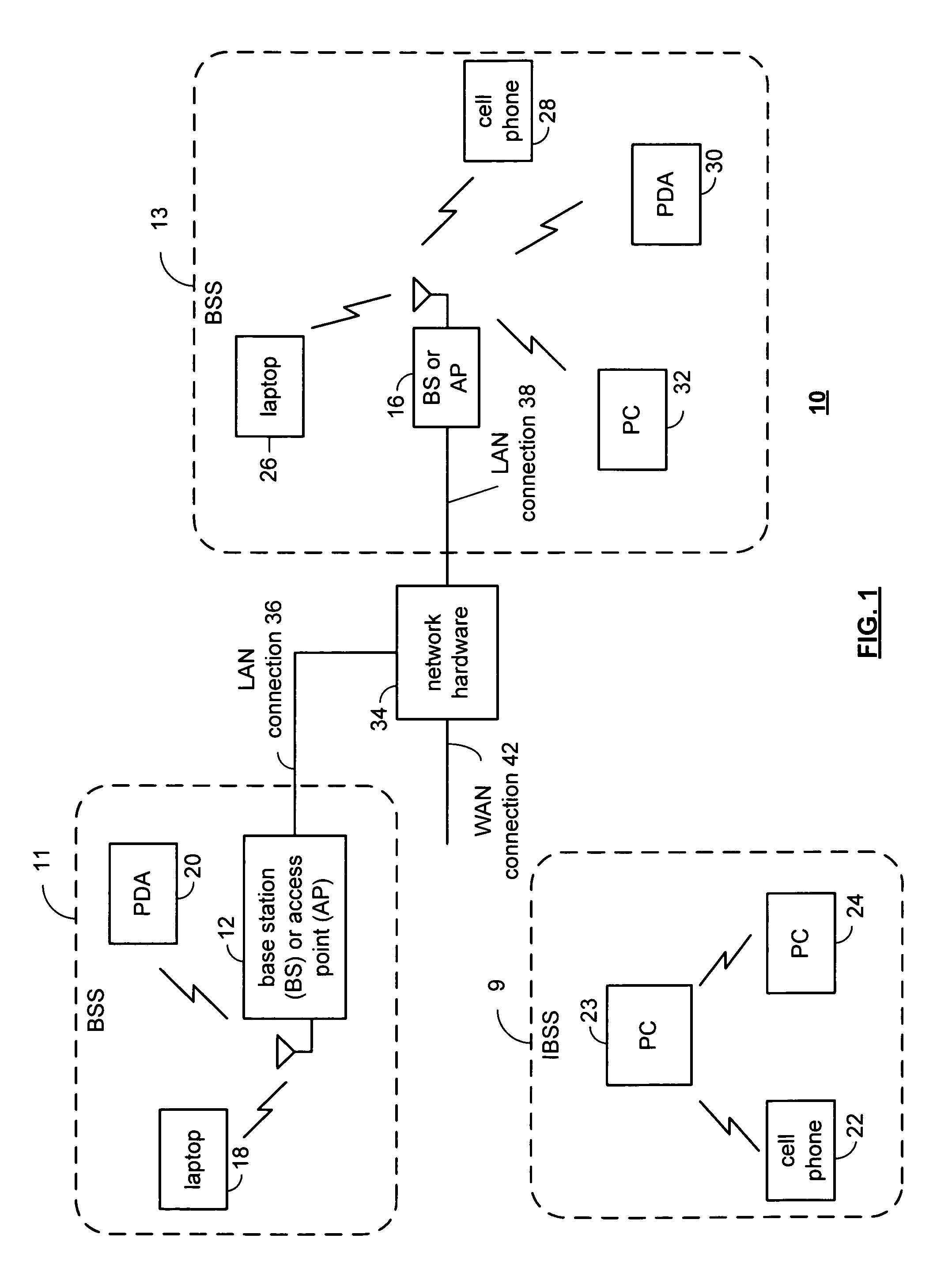
[0038]FIG. 1 is a schematic block diagram illustrating a communication system 10 that includes a plurality of base stations and / or access points 12, 16, a plurality of wireless communication devices 18-32 and a network hardware component 34. Note that the network hardware 34, which may be a router, switch, bridge, modem, system controller, et cetera provides a wide area network connection 42 for the communication system 10. Further note that the wireless communication devices 18-32 may be laptop host computers 18 and 26, personal digital assistant hosts 20 and 30, personal computer hosts 24 and 32 and / or cellular telephone hosts 22 and 28. The details of the wireless communication devices will be described in greater detail with reference to FIG. 2.

[0039]Wireless communication devices 22, 23, and 24 are located within an independent basic service set (IBSS) area and communicate directly (i.e., point to point). In this configuration, these devices 22, 23, and 24 may only communicate ...


PUM


Abstract

An RF transceiver front-end includes receiver and transmitter front-ends. The receiver front-end includes 1st and 2nd antennas, a ninety degree phase shift module and an LNA module. The 1st and 2nd antennas receive inbound RF signals and provide a first directional circular polarization. The ninety degree phase shift module phase shifts the RF signals received by the 2nd antenna. The LNA module amplifies the RF signals received by the 1st antenna and the shifted RF signals. The transmitter front-end includes a PA module and 3rd and 4th antennas, which provide a second directional circular polarization. The PA module amplifies outbound RF signals to produce amplified outbound RF signals and amplified orthogonal outbound RF signals. The 3rd antenna transmits the amplified outbound RF signals and the 4th antenna transmits the amplified orthogonal outbound RF signals.

Description

[0001]This patent application is claiming priority under 35 USC §120 as a continuation-in-part patent application of co-pending patent application entitled PLANER HELICAL ANTENNA, having a filing date of Mar. 21, 2006, and a Ser. No. 11 / 386,247.CROSS REFERENCE TO RELATED PATENTS[0002]NOT APPLICABLESTATEMENT REGARDING FEDERALLY SPONSORED RESEARCH OR DEVELOPMENT[0003]NOT APPLICABLEINCORPORATION-BY-REFERENCE OF MATERIAL SUBMITTED ON A COMPACT DISC[0004]NOT APPLICABLEBACKGROUND OF THE INVENTION[0005]1. Technical Field of the Invention[0006]This invention relates generally to wireless communication systems and more particularly with transmitting and receiving radio frequency (RF) signals.[0007]2. Description of Related Art[0008]Communication systems are known to support wireless and wire lined communications between wireless and / or wire lined communication devices. Such communication systems range from national and / or international cellular telephone systems to the Internet to point-to-p...

Claims


Application Information

Patent Timeline
Patent Type & Authority Patents(United States)
IPC IPC(8): H04B1/06H04B7/00
CPCH01Q1/2216H01Q1/243H01Q1/362H01Q1/38H01Q11/083H04B7/0413H04B7/0617H04B7/10H04B1/02H04B7/08
Inventor YOON, SEUNGHWANDE FLAVIIS, FRANCOROFOUGARAN, AHMADREZA REZA
Owner AVAGO TECH WIRELESS IP SINGAPORE PTE
Why Eureka
Try Eureka