Series-parallel multistage torque converter damper

a torque converter and damper technology, applied in the direction of fluid couplings, couplings, gearing, etc., can solve the problems of not meeting the torque capacity or nvh requirements of current turbine dampers, serious problems with needed capacity and rate, and difficult engine vibration isolation, etc., to achieve different strength and compression characteristics

Inactive Publication Date: 2010-02-09
SCHAEFFLER TECH AG & CO KG
View PDF23 Cites 20 Cited by
  • Summary
  • Abstract
  • Description
  • Claims
  • Application Information

AI Technical Summary

Benefits of technology

[0010]In accordance with the invention, there is therefore provided a reliable high capacity torque converter damper having a large wind up angle where, a lower rate (less torque required per degree of wind up) is initially required with rate progressively increasing as wind up continues.
[0016]At a first stage of operation, in a normal drive direction, spring sets 1 and 2 operate in series and allow a large wind up relative to torque input (low “rate”). At a second stage spring set 3 is introduced in parallel with spring sets 1 and 2 thus allowing less wind-up relative to torque input than in stage one, absorbing more torque per degree of wind-up (intermediate “rate”). At a third stage, spring set 2 is removed from series with spring set 1 thus requiring even more torque per degree of wind-up (high “rate). As previously discussed, the damper may operate in reverse, i.e., as a damper for torque from the transmission to the engine when torque input to the damper from the transmission exceeds torque input to the damper from the engine. Spring set 2 may contain springs of about the same strength as spring set 1 or may contain stronger or weaker springs. Weaker springs than spring set 1 might be advantageous so that the initial rate is lower in the normal (drive or forward) operation direction from the engine to the transmission. In the forward direction, at least one stop between floating apparatus and one of the input device and output device removes springs 2 from series with spring set 1 preventing springs of spring set 2 from bottoming out. Similarly, at least one stop prevents the springs of spring set 2 from bottoming out in the reverse direction.
[0018]Several sets of springs are provided that provide elasticity for permitting damper wind up, i.e., twisting with storage of twisting energy or torque. The springs include a set of drive springs, a set of secondary springs, that may or may not be weaker than the drive springs, and a set of parallel springs that are usually have about the same compression characteristics and about the same strength of the drive springs, but optionally may be of different strength and compression characteristics.
[0019]All of the springs are radially oriented with respect to the output hub and retained by the cover plate, such that upon initial movement of the turbine and attached cover plate, a first end of each of the drive springs is in contact with the cover plate and a second end of each of the drive springs is in contact with the intermediate flange and a first end of each of the secondary springs is in contact with the intermediate flange and a second end of each of the secondary springs is in contact with the output flange such that the drive springs compress and transfer force to and cause the intermediate flange to rotate and to thus compress the secondary springs. The secondary springs in turn cause the output flange and output hub to rotate. The drive and secondary springs initially absorb energy from the turbine and allow it to rotate through a greater angle than the output flange thus compensating for time delay in overcoming initial inertia of the output hub and attached apparatus.
[0020]Parallel springs are held in spaces within the intermediate flange (or within such spaces in the cover plate) longer than the length of the parallel springs such that upon initial rotation of the turbine, the parallel springs do not transfer torque from the cover plate to the intermediate flange but upon sufficient compression of the drive and secondary springs, the cover plate moves sufficiently far (winds up sufficiently far) relative to the intermediate flange that the parallel springs contact both the cover plate and the intermediate flange so the parallel springs transfer torque from the cover plate to the intermediate flange and subsequently to the output flange in parallel with the drive springs further increasing torque capacity transfer to the output flange as torque increases.

Problems solved by technology

The utilization of “variable displacement” engines operating in four or eight cylinder mode has made engine vibration isolation more difficult and there is thus a need for a damper having increased control and damper capacity (torque absorbing capacity for storage as potential energy that can be released to smooth torque transfer) due to a torque increase in the engine.
Current turbine dampers will not meet the torque capacity or NVH requirements needed for transfer of torque in four or eight cylinder modes of newer variable displacement engines to a transmission and vice-versa.
Single stage and even dual stage turbine dampers are already commercially available to reduce torque converter vibration isolation from the drive of an engine but still have serious problems with needed capacity and rate.
Further such known turbine dampers may require a large envelope space, i.e., space taken by the damper in the power train and may have a large hysteresis, i.e., energy loss primarily through friction during damper operation.
It has been known that a series of complete dampers could accomplish the task of capacity and lower rate but not without serious disadvantages, in particular with respect to complexity in cooperative operation, expense, envelope space, hysteresis and balance.
This damper has a significant disadvantage, apparently not recognized by the inventors, in that the series of springs 58A and 58B are weak relative to 59 and 60.
Bottoming out causes outwardly bowing damaging forces on the springs.
Such an arrangement has definite disadvantages in that the inside spring must necessarily be of a smaller diameter than the outside spring and is thus usually significantly weaker.
This of course limits the usable strength of the outside spring by parameters unrelated to space and length.
Further, the weaker spring can never be removed from torque transfer.
Additionally, when it is desirable to match characteristics of the inside and outside springs, e.g., so the converter has similar characteristics in both rotational directions, such matching is difficult and in fact cannot be realistically completely accomplished due to the drastically different spring diameters.
Another disadvantage is that multiple inventories of different spring types have to be maintained and properly used.

Method used


Image

  • Series-parallel multistage torque converter damper
  • Series-parallel multistage torque converter damper
  • Series-parallel multistage torque converter damper

Examples


Embodiment Construction

[0038]In discussing the present invention the following definitions are used:

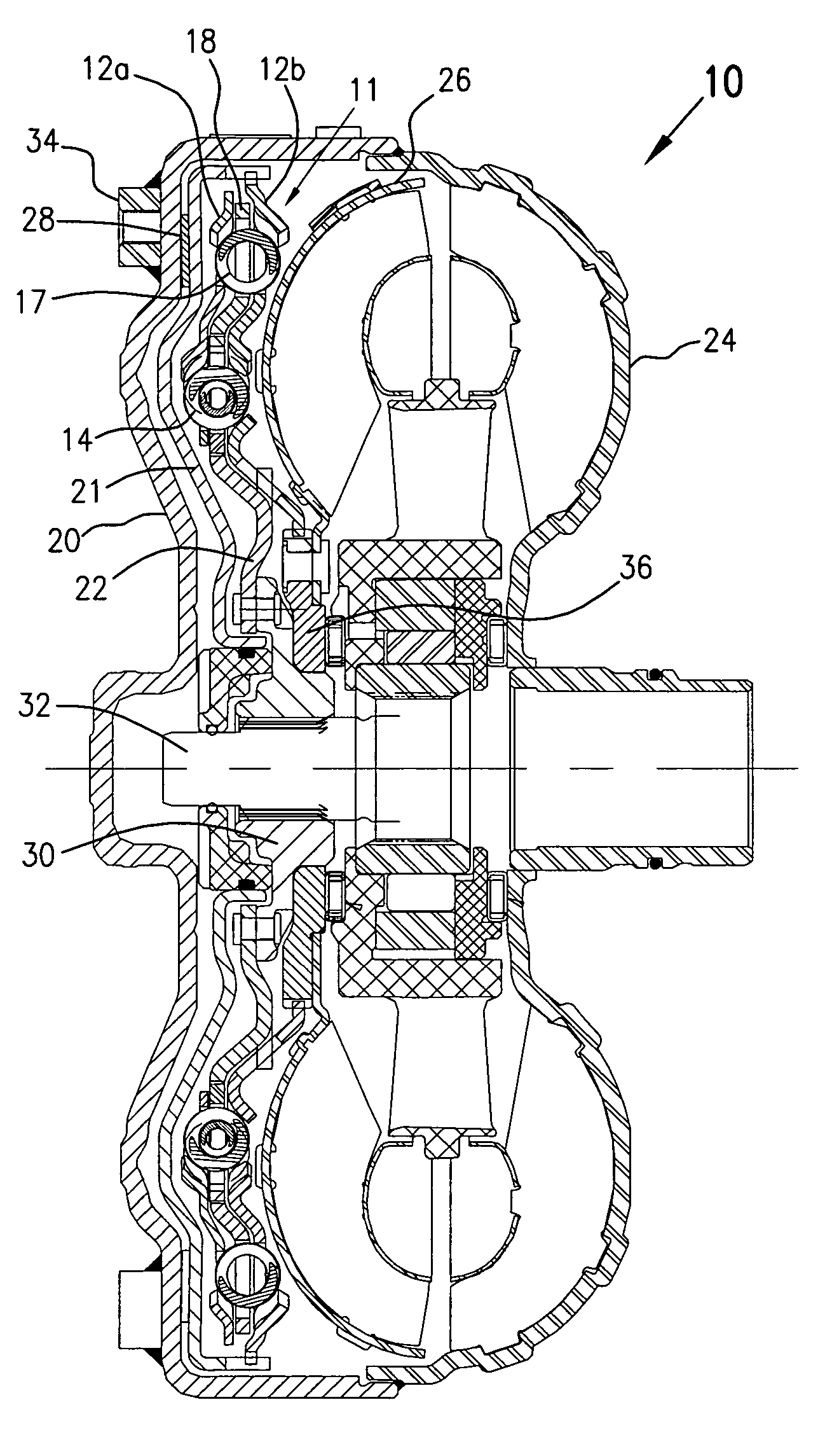
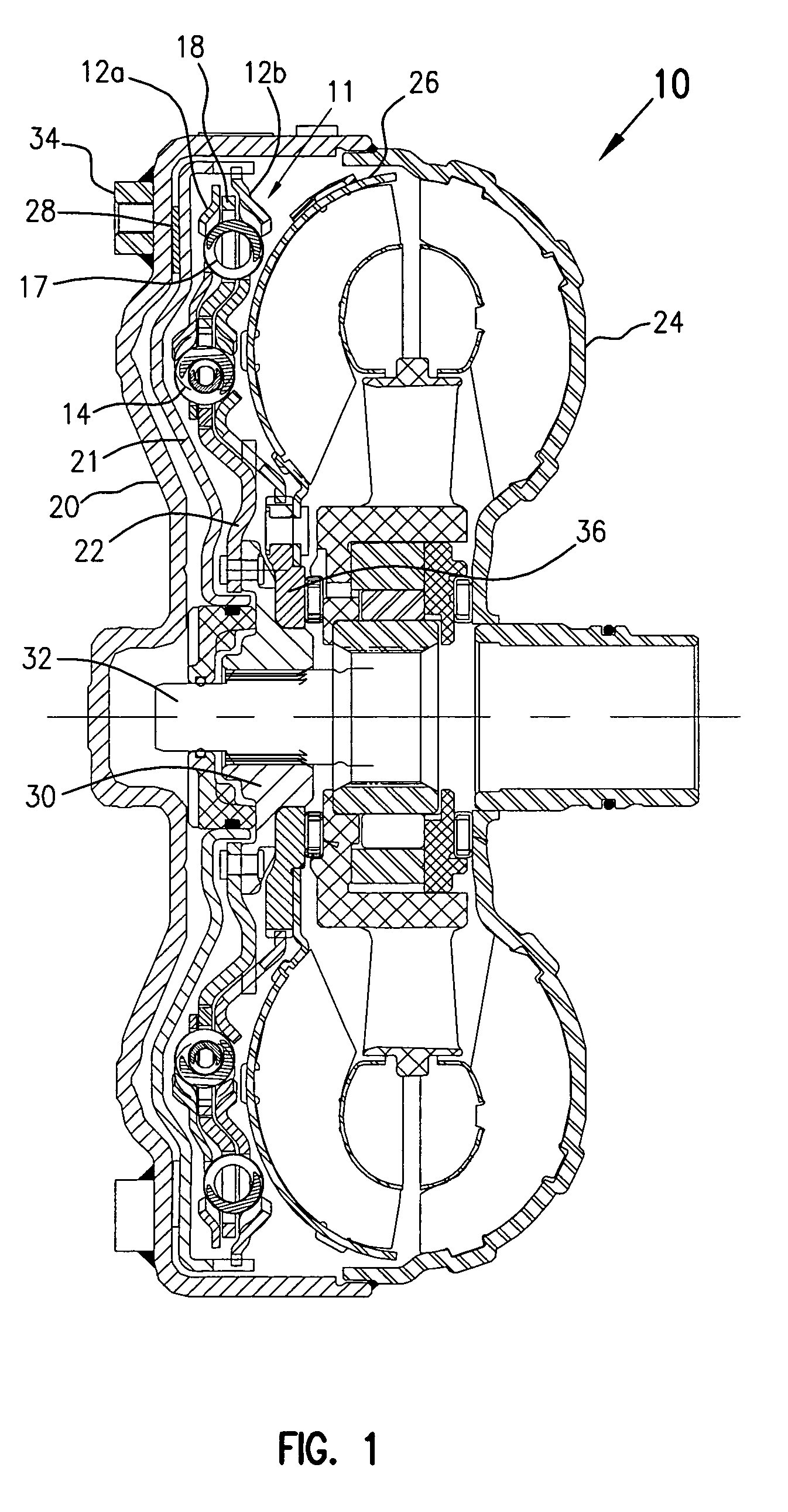
[0039]“Wind-up angle” is the relative angle between the cover plate of the damper and the output flange starting at zero degrees from a “free” position.

[0040]“Free position” is the position where all springs have minimum applied compressive force.

[0041]“Damper capacity” is the torque absorbing ability, commonly measured in Newton-meters, which absorbed torque is held as potential energy until released.

[0042]“Rate” of wind-up is the amount of absorbed torque per wind-up degree.

[0043]“Hysteresis” is energy loss, mostly due to friction, during wind-up and return to a free position.

[0044]“Envelope space” is the space required in the system to hold the damper.

[0045]“Damper Input” is intended to mean energy input into the damper, either in a direction from the turbine / engine or in a direction from the transmission. For convenience in description, the input is described as coming from the turbine toward the transm...


PUM


Abstract

A method and apparatus for damping torque output from a torque converter turbine to input to a transmission. The damper includes: (a) an input device for connection to an engine; (b) a first spring set having drive springs; (c) a second spring set having secondary springs; (d) a third spring set having parallel springs; (e) a floating apparatus; and (f) an output device. Springs of the first spring set are compressible in a forward direction toward the output device as a result of torque applied to the input device and compressible in a reverse direction toward the input device as a result of torque applied by the output device. The first and second spring sets are in series between the input device and output device during a first forward compression of the first spring set, and the series is in parallel with the third spring set between the input apparatus and output device during a second compression of the first spring set. The first spring set is in parallel with the third spring set between the input apparatus and output device without the second spring set during a third compression of the first spring set. The floating apparatus is between the input apparatus and the output device and between springs of said first and second spring sets during the first forward compression of the first spring set. The method includes the steps of: (a) operating a spring set one and a spring set two in series between torque input and torque output; (b) placing a spring set three in parallel with spring sets one and two allowing more torque per degree of wind-up than in step (a); and (c) removing spring set two from series with spring set one resulting more torque per degree of wind-up than in step (b).

Description

[0001]This application claims the benefit of U.S. Provisional patent application Ser. No. 60 / 715,034, filed on Sep. 8, 2005, which is expressly incorporated by reference herein.BACKGROUND OF THE INVENTION[0002]This invention relates to dampers for torque converters and especially relates to such torque converters where coils springs are inserted in the torque transfer path between the turbine of the torque converter and an output shaft to a transmission to dampen sudden energy or torque changes between the turbine and the output shaft.[0003]The utilization of “variable displacement” engines operating in four or eight cylinder mode has made engine vibration isolation more difficult and there is thus a need for a damper having increased control and damper capacity (torque absorbing capacity for storage as potential energy that can be released to smooth torque transfer) due to a torque increase in the engine. A lower rate, i.e., torque capacity per degree of wind up, is also desirable ...

Claims


Application Information

Patent Timeline
Patent Type & Authority Patents(United States)
IPC IPC(8): F16F15/121
CPCF16F15/12366F16H45/02F16H2045/0226F16H2045/0231F16H2045/0247F16H2045/0294
Inventor AVINS, DAVIDMACDONALD, FRASERFRARY, MATTHEW
Owner SCHAEFFLER TECH AG & CO KG
Why Eureka
Try Eureka