Lawn equipment minimal track wheel

a technology of track wheel and lawn equipment, applied in the field of lawn equipment minimal track wheel, can solve the problems of excessive and vain lawn patterns of homeowners, and achieve the effect of greater traction

Inactive Publication Date: 2010-02-16
BURNS WILLIAM RANDALL
View PDF17 Cites 9 Cited by
  • Summary
  • Abstract
  • Description
  • Claims
  • Application Information

AI Technical Summary

Problems solved by technology

While most homeowners take pride in having well groomed lawns, some homeowners find intentional or unintentional patterns in their lawns excessive and in vain.

Method used


Image

  • Lawn equipment minimal track wheel
  • Lawn equipment minimal track wheel
  • Lawn equipment minimal track wheel

Examples


third embodiment

[0033]FIG. 11 shows the wheel, denoted 10C, designed to connect to an axle bolt 42 that extends laterally from a short neck 71 integrally formed on the lawn mower's outer housing or bracket 9. The wheel 10C uses a third hub plate 55 with a recessed neck opening 56 formed thereon designed to receive the short neck 71 on the housing or bracket 9. The center axle bore 58 formed on the inside disc 25 is slightly larger so that the recessed neck opening 56 formed on the hub plate 55 may partially extend into the inner disc 25. A threaded bore is formed on the short neck 71 that connects to the threads on the axle bolt 42.

fourth embodiment

[0034]FIG. 13 depicts the invention generally indicated by the reference number 10D in which the two discs, inner spacer 35, and bushing or bearing are integrally formed in a single structure. Wheel 10D includes a spool body 101 with outer and inner disc flanges 102, 104, respectively, separated by a narrow neck 106. Extended transversely through the spool body 101 is an axle bore 108 designed to receive the axle bolt 42. Formed on the outside surface of the outer disc flange 102 is a circular recessed cap region 110 designed to receive the head of the bolt 42, a washer 46 and the side walls 113 of a removable hubcap 112. The hubcap 112 includes a central cavity 114 designed to receive the head of the axle bolt that extends through the bracket 120. The inside surface 103 of the spool body 101 is flat thereby enabling the wheel 10D to rotate smoothly around the threaded end of bolt 42 and extend through a hole formed on the bracket 120. A standard washer 115, a lock washer 116 and a ...

fifth embodiment

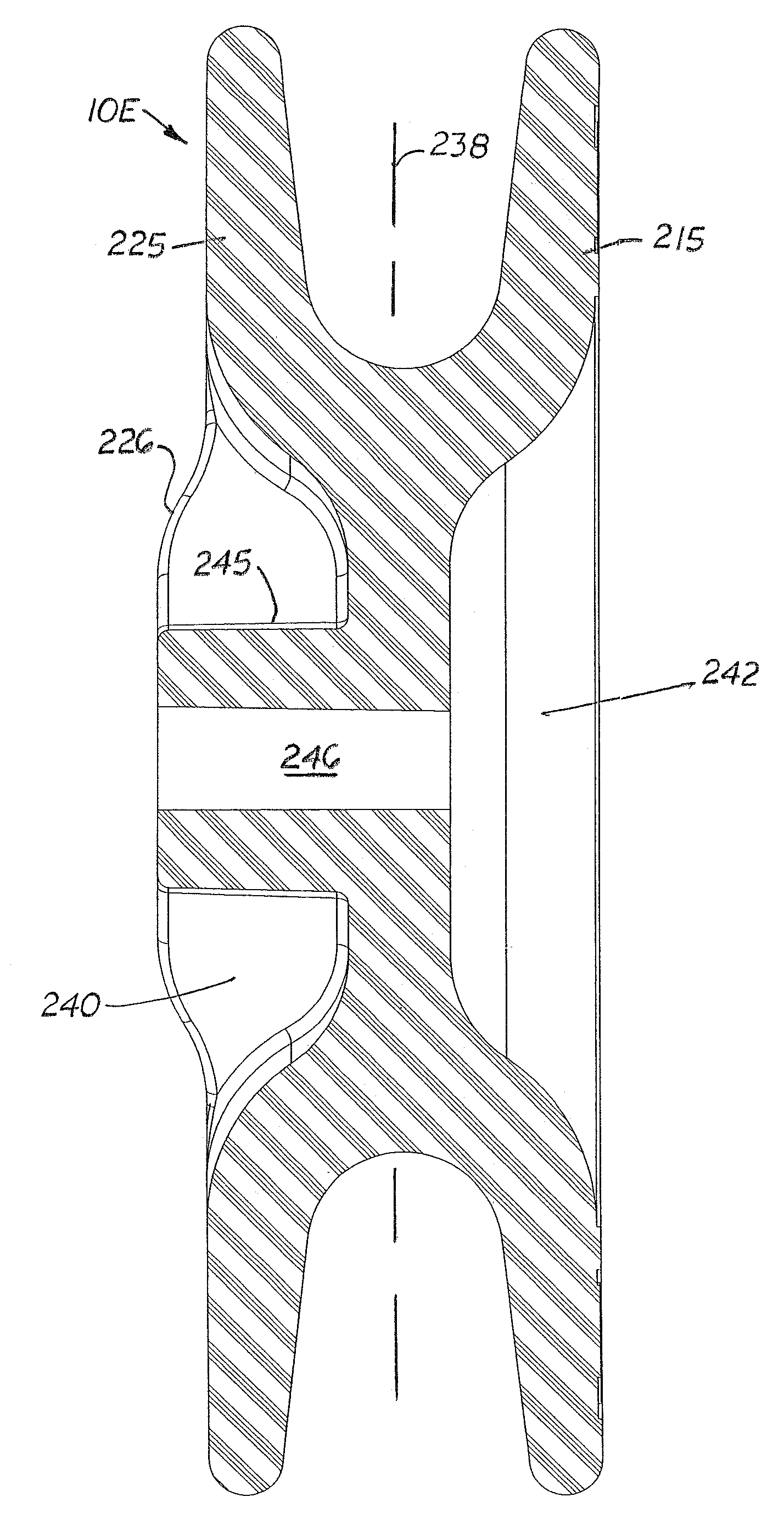
[0037]FIGS. 15-17 show the wheel 10E with two, integrally formed outer and inner discs 215, 225 on a centrally located, circular spacer 235. The spacer 235 includes a intermediate section 237 located along the vertical center axis designated 238 on the wheel 10E. Formed on the opposite discs on the wheel 10E are two inner and outer cavities, 240 and 242, respectively. Located centrally in the inner cavity 240 is an inward extending axle neck 245. The circular portion 226 of the inner disc 225 located adjacent to the inner cavity 240 extends inward and acts as a stop surface for the wheel against the lawn mower (not shown). The length of the axle neck 245 is sufficient so that the end of the axle neck 245 is flush or even with the portion 226. Formed inside the axle neck 245 is a passageway 246 designed to receive an axle bolt.


PUM


Abstract

A wheel for a piece of lawn equipment specifically designed not to produce tracks in the lawn as the lawn equipment moves over the lawn. The wheel is made of two parallel circular discs spaced apart by a center spacer. The two discs are relatively thin and thereby have minimal contact with the grass blades when rolling over the lawn. The height of the wheel and the diameter of the axle are sufficient so that glass blades on the lawn are not bent downward and extend upward between the two discs. An optional ring structure made of rubber or similar material is attached over the perimeter edge of each disc to provide greater traction and to protect the edge from damage. Located inside the wheel axle is an optional bushing or wheel bearing.

Description

FIELD OF THE INVENTION[0001]This utility patent application is based on the provisional patent application (Ser. No. 60 / 578,752) filed on Jun. 10, 2004.BACKGROUND OF THE INVENTIONDescription of the Related Art[0002]Lawn mowers typically have one or two pairs of wheels mounted on the opposite sides of the mower's housing that hold the housing a desired distance above the lawn. The wheels are typically mounted on adjustable brackets that allow the height of the lawn mower housing to be adjusted. During use, the wheels on the housing creates tracks in the lawn as shown in FIG. 1.[0003]Recently, it has become popular to attach a roller behind the housing that bends the grass downward as the mower travels over the lawn. By moving the mower in different directions, decorative patterns may be created in the lawn. Such patterns are commonly seen on the infield and outfield areas on a baseball field.[0004]While most homeowners take pride in having well groomed lawns, some homeowners find int...

Claims


Application Information

Patent Timeline
Patent Type & Authority Patents(United States)
IPC IPC(8): A01D34/00A47B91/00A63C17/22A01D34/03
CPCA01D34/001Y10T16/184
Inventor BURNS, WILLIAM RANDALL
Owner BURNS WILLIAM RANDALL
Why Eureka
Try Eureka