Method for verifying the integrity of thermal desorption sampling tubes

a sampling tube and thermal desorption technology, applied in the direction of material analysis, separation processes, instruments, etc., can solve the problems of introducing errors into the analytical process, and assuming the validity of data, so as to achieve the effect of quick loading

Active Publication Date: 2010-02-16
PERKINELMER U S LLC
View PDF12 Cites 20 Cited by
  • Summary
  • Abstract
  • Description
  • Claims
  • Application Information

AI Technical Summary

Benefits of technology

[0009]This technique compensates for instrumental variations that may affect the analytical results—both the standard gas compound and each analyte are subjected to the same variations and so their relative responses provide a more valid quantitative measure of the amount of analyte present.
[0010]To provide a full analytical control, the standard gas is added before the tube is used to take a sample. The standard gas addition accessory may be modified to add the gas standard to clean adsorbent tubes but not apply the thermal desorption step. In this way, for example, a full set of 50 sample tubes in an automated thermal desorption (ATD) system can be quickly loaded with the IS.

Problems solved by technology

However, if proper care is not taken in the process of handling, sampling, storing and analyzing the tubes, errors may be introduced into the analytical results because of sample leakage from the tube or ingress of compounds from the storage equipment.
Unfortunately, there has been no mechanism to ascertain whether such leakage has occurred and so, the validity of the data must be assumed.

Method used


Image

  • Method for verifying the integrity of thermal desorption sampling tubes
  • Method for verifying the integrity of thermal desorption sampling tubes
  • Method for verifying the integrity of thermal desorption sampling tubes

Examples


Embodiment Construction

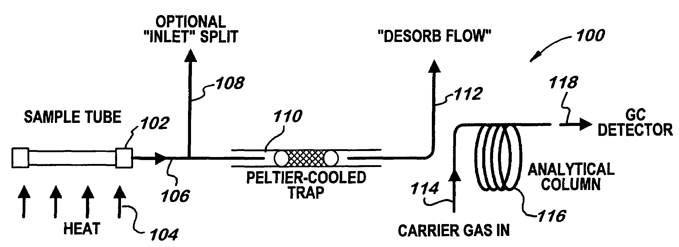
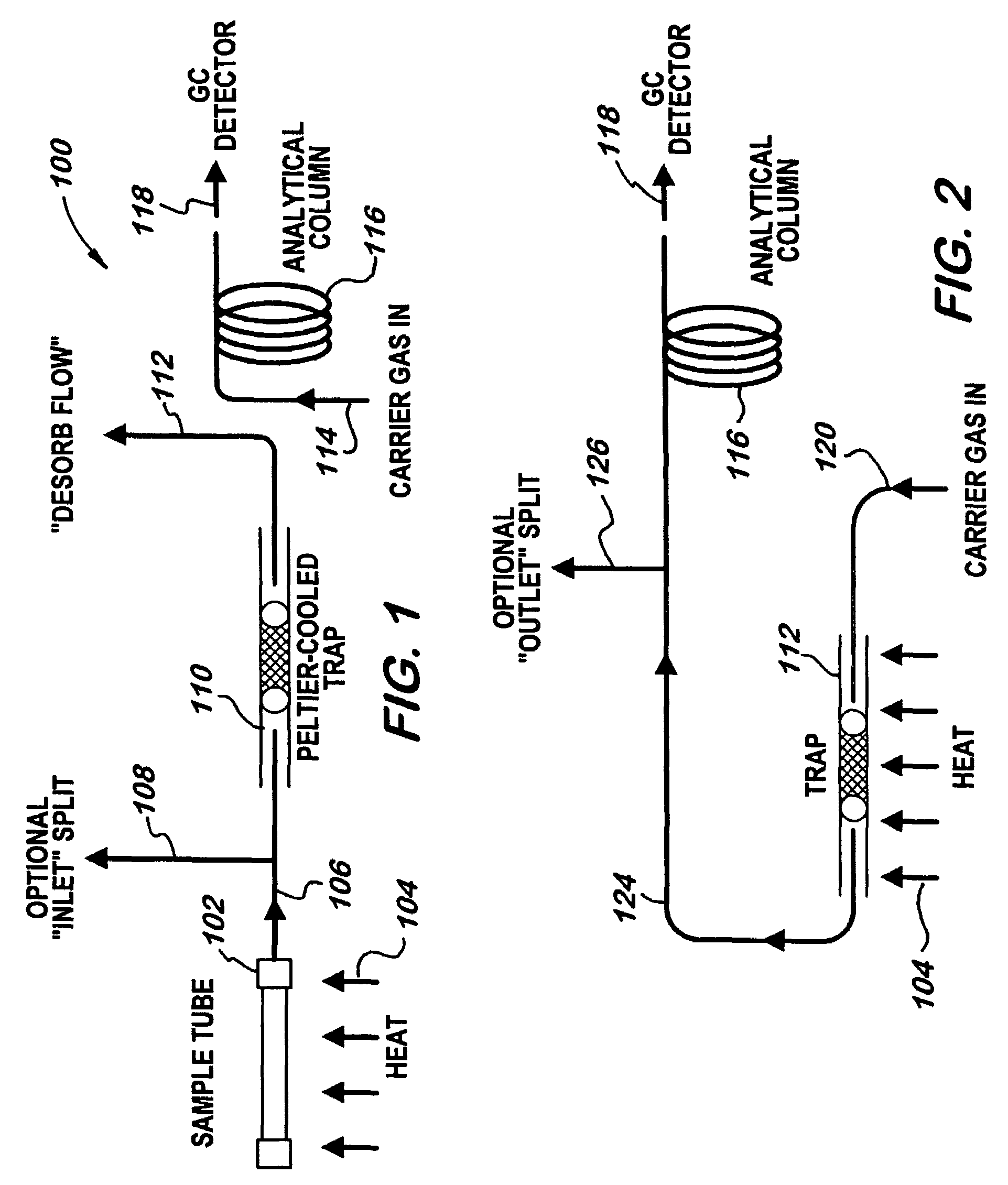
[0020]FIG. 1 is a schematic drawing showing a thermal desorption apparatus for tube desorption. FIG. 2 is a schematic drawing showing a thermal desorption apparatus for trap desorption.

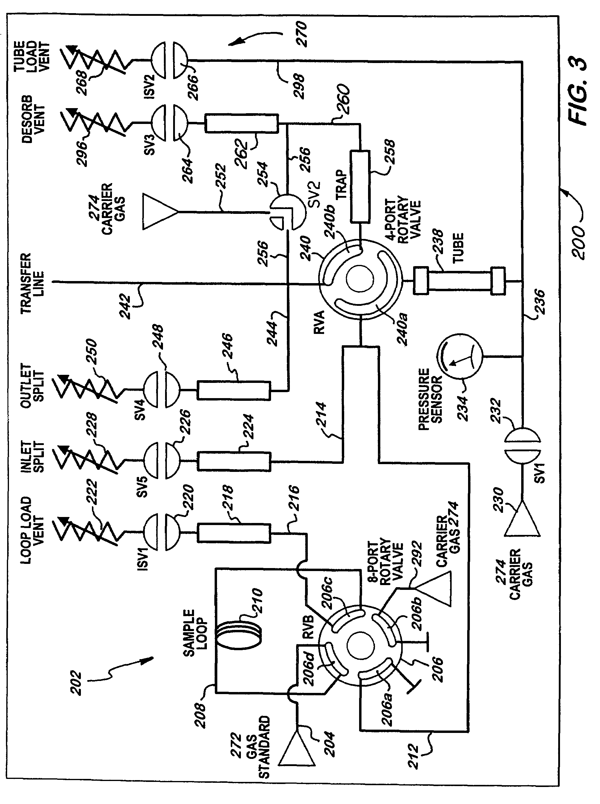
[0021]A thermal desorption system is shown generally in FIG. 3 at 200. The thermal desorption system 200 comprises a first rotary valve (RVB) 206 which includes a set of ports 206a, 206b, 206c, 206d. The ports 206a, 206b, 206c, 206d include a fluid inlet segment and a fluid outlet segment. The first rotary valve 206 is in fluid communication with a standard gas 272 via a conduit 204 at port 206d. A conduit 208, which includes a sample loop 210, provides fluid communication between port 206d and port 206c of the first rotary valve 206. A loop load vent 216, which includes a filter 218, such as a charcoal filter, a valve 220 (ISV1) and a flow regulator 222, vents the first rotary valve 206 from port 206c. The first rotary valve 206 is also in fluid communication with a carrier gas 274 via a conduit 292 ...


PUM

PropertyMeasurementUnit
volumeaaaaaaaaaa
compositionaaaaaaaaaa
mass spectrumaaaaaaaaaa

Abstract

An analyte of a sample is transferred to an analytical instrument by introducing a quantity of a compound of a standard material into a vessel containing an adsorbent material; introducing a quantity of the analyte of the sample into the vessel; and transferring the analyte of the sample and the compound of the standard material to the analytical instrument.

Description

PRIOR APPLICATIONS[0001]This application is a continuation of pending International Patent Application No. PCT / US2004 / 016555 filed on May 24, 2004 which designates the United States, and which claims the benefit of, under 35 U.S.C. §119(e), U.S. Provisional Patent Application Ser. No. 60 / 472,854 filed May 23, 2003 which is incorporated herein by reference as if set forth at length.FIELD OF THE INVENTION[0002]This invention relates to a method and apparatus for verifying the integrity of thermal desorption sampling tubes.BACKGROUND OF THE INVENTION[0003]The Environmental Protection Agency (EPA) establishes standards against which the relative abundance of compounds in samples may be compared and thus the compound may be determined. For example, through the use of standard compounds such as bromoflurobenzene (BFB) and decaflurotriphenylphosphine (DFTPP) volatile and semi-volatile organic compounds in water may be analyzed. The standard compounds are injected into a gas chromatograph-m...

Claims


Application Information

Patent Timeline
Patent Type & Authority Patents(United States)
IPC IPC(8): G01N35/00G01N1/22G01N30/06G01N30/08G01N30/12G01N30/62
CPCG01N30/06G01N33/0011G01N1/2214Y10T436/2575G01N2030/128G01N2030/625Y10T436/11G01N2030/085
Inventor TIPLER, ANDREWDELORENZO, FRANK
Owner PERKINELMER U S LLC
Why Eureka
Try Eureka