System and method for converting wind into mechanical energy for a building and the like

a technology of mechanical energy and airflow, applied in the direction of fluid couplings, renewable energy generation, greenhouse gas reduction, etc., can solve the problems of material fatigue and catastrophic failure, many technical, environmental, noise and aesthetic problems, and raise safety concerns, so as to improve the performance of the internal combustion engine, improve efficiency, and improve structural strength

Inactive Publication Date: 2010-02-16
MARQUISS WIND POWER
View PDF53 Cites 28 Cited by
  • Summary
  • Abstract
  • Description
  • Claims
  • Application Information

AI Technical Summary

Benefits of technology

[0009]The present invention relates to a wind energy collection system constructed from one or more airfoils with substantially stationary wind contacting surfaces, a substantially flat leading edge and a scoop for improved efficiency.
[0020]In accordance with another embodiment, a system for improving performance of an internal combustion engine comprises: an exhaust pipe; and a leading edge member attached at one end of the exhaust pipe.
[0021]The present invention provides the advantages of improved efficiency and improved structural strength in a system for converting an airflow into mechanical energy with substantially stationary wind contacting surfaces.

Problems solved by technology

These classic windmills with exposed rotating blades pose many technical, safety, environmental, noise, and aesthetic problems.
The technical problems may include mechanical stress, susceptibility to wind gusts and shadow shock, active propeller blade pitch control and steering, and frequent dynamic instabilities which may lead to material fatigue and catastrophic failure.
In addition, the exposed propeller blades may raise safety concerns and generate significant noise.
Furthermore, horizontal axis wind turbines cannot take advantage of high energy, high velocity winds because the turbines can be overloaded causing damage or failure.
Since wind energy increases as the cube of velocity, this represents a significant disadvantage in that high wind velocities, which offer high levels of energy, also require that the windmills be governed.
Although vertical axis turbines address many of the shortcomings of horizontal shaft windmills, they have their own inherent problems.
The continual rotation of the blades into and away from the wind causes a cyclical mechanical stress that soon induces material fatigue and failure.
Also, vertical axis wind turbines are often difficult to start and have been shown to be lower in overall efficiency.
In contrast, other building-integrated designs often appear as clumsy arrangements utilizing oversized props and contrived ducts.
Yet the suburban / urban market is not only the fastest growing demand for electrical energy, it is also the least likely to support a generational facility.
Even the utilities recognize that this is a problem.

Method used


Image

  • System and method for converting wind into mechanical energy for a building and the like
  • System and method for converting wind into mechanical energy for a building and the like
  • System and method for converting wind into mechanical energy for a building and the like

Examples


Embodiment Construction

[0053]This invention provides a system for converting an airflow into mechanical energy with non-moving wind contacting parts and which provides improved efficiency with a stronger, simpler construction.

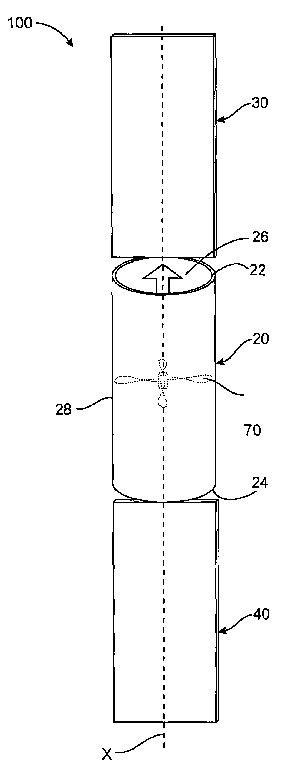
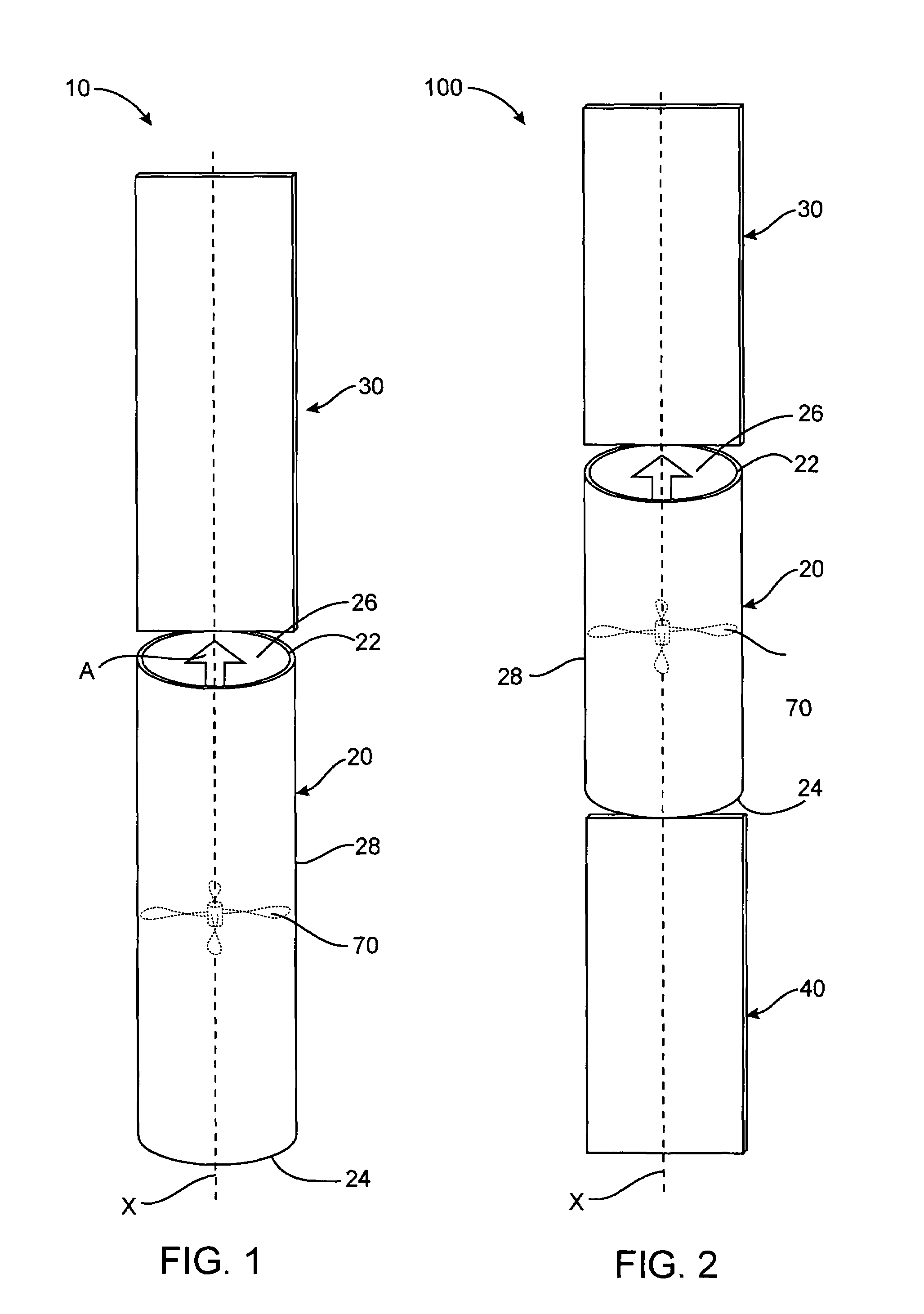
[0054]FIG. 1 shows a drawtube 10 for converting an airflow into mechanical energy having a tubular member 20, a substantially planar leading edge member 30, and an energy conversion device 70. The wind in FIG. 1 is assumed to be coming out of the page. The energy conversion device 70 may be positioned within the tubular member 20 as shown in FIG. 1 or connected to the drawtube 10 by an air plenum. The tubular member 20 has a first opening 22 and a second opening 24 formed in two planes substantially perpendicular to a longitudinal axis X of the tubular member. The substantially planar leading edge member 30 is positioned in front of or on the windward side of the first opening 22. The leading edge member 30 in the embodiment of FIG. 1 is in a plane, which is substantially parallel to...


PUM


Abstract

A system for converting an airflow into mechanical or electrical energy and dimensioned to be attachable to a structure. The system includes a leading edge member, a pair of drawtube arrays, and an energy conversion device located between the pair of drawtube arrays and configured to convert an airflow through the channel into mechanical or electrical energy.

Description

CROSS REFERENCE TO RELATED APPLICATIONS[0001]This application is a Continuation in part of U.S. patent application Ser. No. 11 / 104,673, filed Apr. 13, 2005, now U.S. Pat. No. 7,199,486, which is a Continuation of U.S. patent application Ser. No. 10 / 619,732, filed Jul. 14, 2003, now U.S. Pat. No. 6,911,744, which are incorporated by reference herein in their entirety.FIELD OF THE INVENTION[0002]The invention relates to a system and method for converting an airflow into mechanical energy for a building and the like, and more particularly, the invention relates to a system and method for collecting wind energy and converting the wind energy into useful energy forms.BACKGROUND OF THE INVENTION[0003]Many wind energy collection systems have been proposed in the prior art. Classic windmills and wind turbines employ vanes or propeller surfaces to engage a wind stream and convert the energy in the wind stream into rotation of a horizontal windmill shaft. These classic windmills with exposed ...

Claims


Application Information

Patent Timeline
Patent Type & Authority Patents(United States)
IPC IPC(8): F03B9/00F01N13/10
CPCF03D1/04F03D3/06F03D11/04F05B2240/122F05B2240/13F05B2240/131F05B2240/40F05B2240/911Y02B10/30Y02E10/728Y02E10/74F03D9/25F03D9/34F03D13/20Y02E10/72
Inventor ROSKEY, JOHN E.
Owner MARQUISS WIND POWER
Why Eureka
Try Eureka