Antenna system for sharing of operation

a technology of an antenna system and an antenna array, applied in the direction of polarised antenna unit combinations, individually energised antenna arrays, polarisation/directional diversity, etc., can solve the problems of introducing 50% power loss for each 3 db combiner, and reducing the flexibility of signal polarisation options

Inactive Publication Date: 2010-02-16
QUINTEL TECH
View PDF18 Cites 12 Cited by
  • Summary
  • Abstract
  • Description
  • Claims
  • Application Information

AI Technical Summary

Benefits of technology

[0027]The method provides a like advantage to that of the antenna system aspect of the invention.

Problems solved by technology

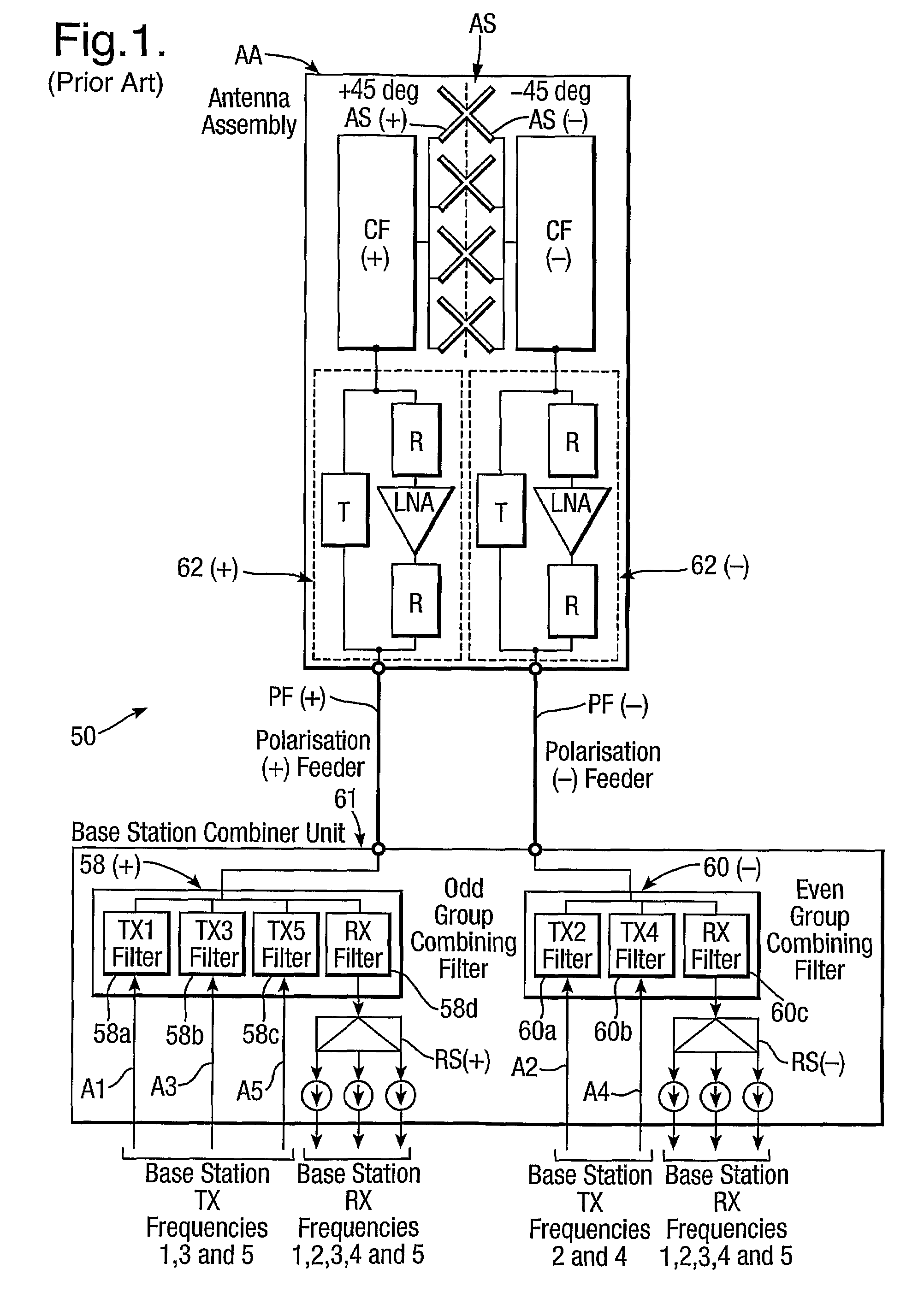
However, it introduces problems of RF signal power losses in signal combining, and reduced flexibility as regards signal polarisation options.
RF signal power losses in signal combining occur as follows: in transmit mode, it is important to avoid mixing of different transmit frequencies, because this gives rise to unwanted intermodulation products.
Resistive loads have the function of dissipating RF power which cannot usefully be employed, and must be disposed of to avoid undesirable effects on required signals; each 3 dB combiner consequently introduces a 50% power loss.
Slant polarisation is known to improve communications performance in the case of received signals, but it is not an optimum polarisation for transmit signals.
This is because a receive antenna in a mobile telephone handset may become oriented orthogonally to a slant polarised transmit signal or nearly or effectively so (having regard to signal reflections), which results in partial or even complete loss of received signal at the handset.

Method used


Image

  • Antenna system for sharing of operation
  • Antenna system for sharing of operation
  • Antenna system for sharing of operation

Examples


embodiment 100

[0088]FIG. 5 shows a further embodiment of an antenna system of the invention indicated generally by 200. It provides circular polarisation for transmit signals and slant polarisation for received signals. It is equivalent to the earlier embodiment 100 described with reference to FIG. 2 with additional transmit filters T and changes to connections to a quadrature hybrid 210 inserted in transmit signal paths. Parts equivalent to those described with reference to FIG. 2 are like referenced with—in the case of numerical references only—a prefix 200 replacing 100. Elements in FIG. 5 which are equivalent to and have the same mode of operation as like referenced elements of FIG. 2 will not be described. Description of FIG. 5 will be directed to aspects of difference.

[0089]Ignoring the additional transmit filters T, the main change to the antenna system 200 compared to the earlier embodiment 100 is that received signals are now not connected to the hybrid 210, they bypass it. Transmit sign...

embodiment 200

[0092]It is possible to produce another variant of the embodiment 200 by exchanging transmit and received signal paths: i.e. in the variant, transmit signals bypass the hybrid 210 and received signals pass through it instead of vice versa. Consequently, the variant is preferentially sensitive to received signals with circular polarisation; transmit signals are radiated from mutually orthogonally slant polarised antenna dipole elements, and therefore become orthogonal slant polarised signals. Rearranging FIG. 5 to implement this is straightforward and will not be described.

[0093]The embodiment 100, FIGS. 3 and 4, the embodiment 200 and the variant referred to above demonstrate that the invention provides control over polarisation in one of or both of transmit and receive modes for a variety of antenna types. In particular, it is possible to use an antenna stack with orthogonal antenna elements giving e.g. +45 degree polarisation and −45 degree slant polarisation but with prearranged ...


PUM


Abstract

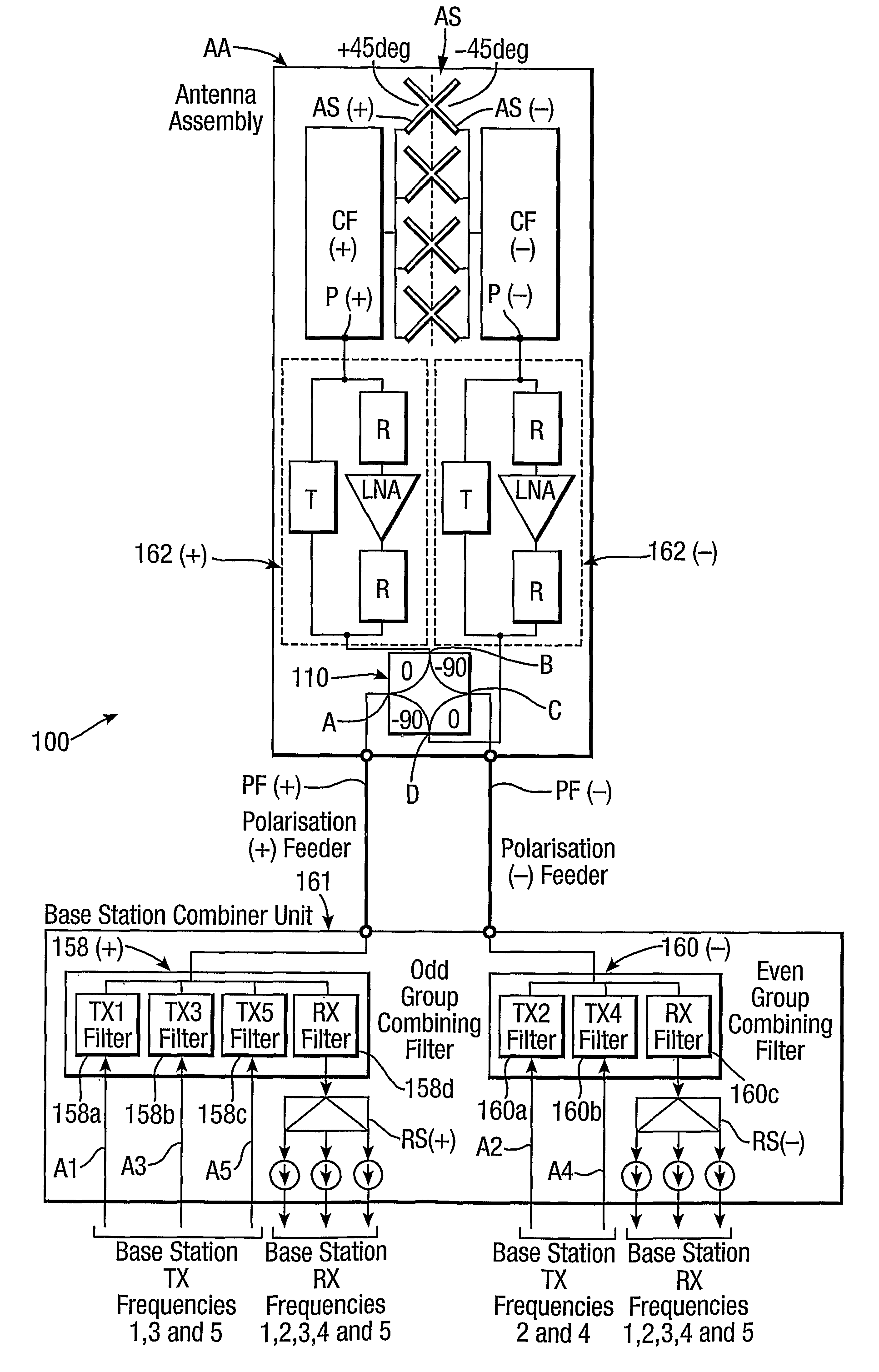
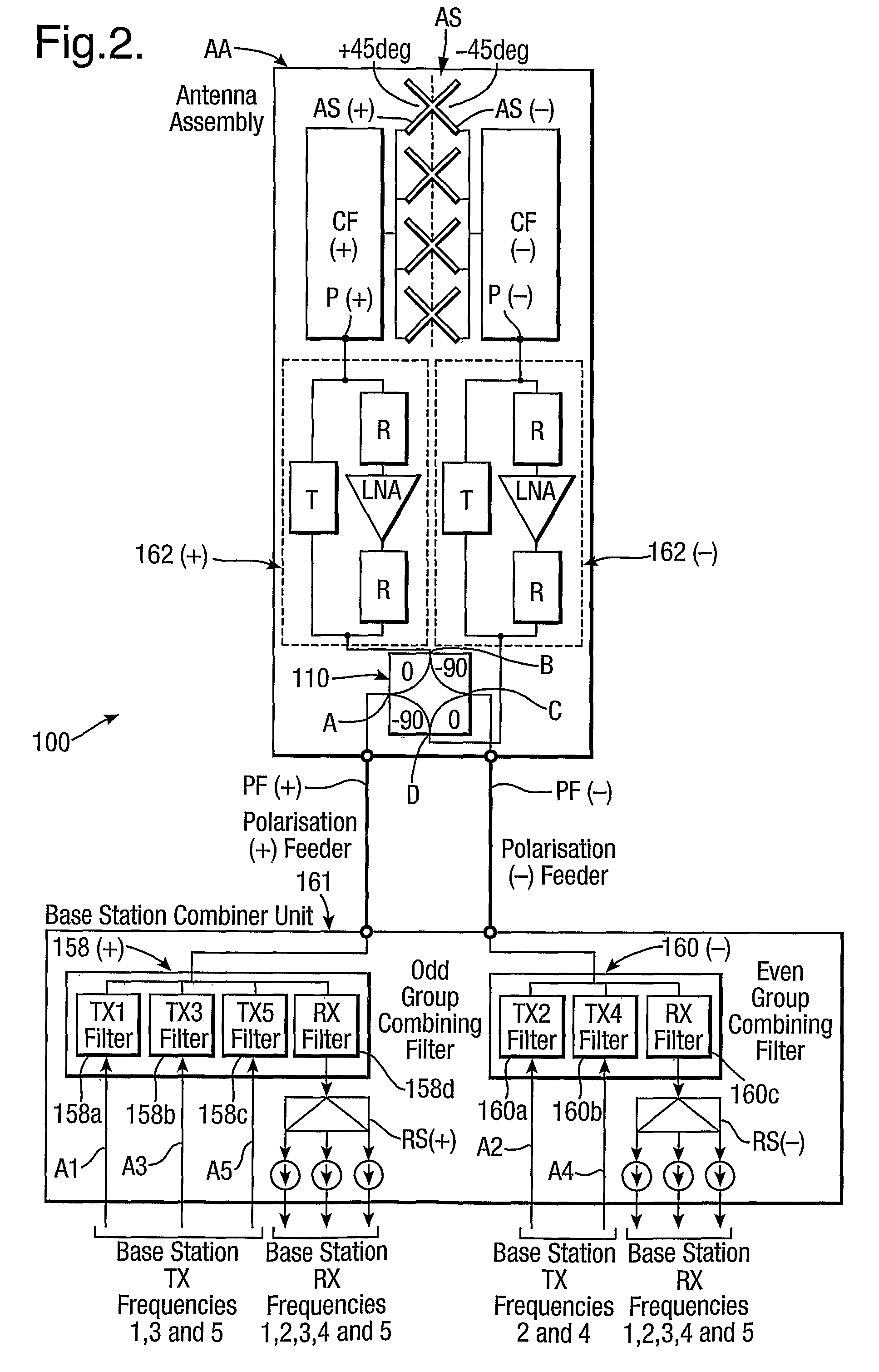
An antenna system for sharing of operation employs contiguous transmit frequencies. Transmit frequencies are separated into non-contiguous sub-groups isolated from one another by filters 158(+) and 160(−) associated with positive and negative polarization. Received frequencies are filtered and split into five signals for input to base station receive ports. Non-contiguous transmit frequency sub-groups are combined by a quadrature hybrid 110 and pass with 90 degree relative phase shift to mutually orthogonal antenna stack ports P(+) and P(−) associated with orthogonally polarized sets of antenna elements AS(+) and AS(−): the ports P(+) and P(−) are isolated from one another by the hybrid 110. The 90 degree phase shift results in one transmit subgroup being radiated with left hand circular polarization and the other transmit subgroup being radiated with right hand circular polarization. Changing the relative phase shift changes the radiated polarization to linear or elliptical, and signal amplitude weighting provides control of antenna beam polarization direction.

Description

BACKGROUND OF THE INVENTION[0001](1) Field of the Invention[0002]This invention relates to an antenna system for sharing of operation by a number of operators, and, more particularly but not exclusively, to such a system for use in cellular mobile radio systems. The antenna system of the invention is intended for use in many phased array applications such as radar and telecommunications, but finds particular application in cellular mobile radio networks, commonly referred to as mobile telephone networks. Such networks include the second generation (2G) mobile telephone networks such as the GSM, CDMA (IS95), D-AMPS (IS136) and PCS systems, and third generation (3G) mobile telephone networks such as the Universal Mobile Telephone System (UMTS), and other cellular radio systems.[0003](2) Description of the Art[0004]Operators of conventional cellular radio networks generally employ their own base stations each of which is connected to one or more antennas. Because the numbers of cellula...

Claims


Application Information

Patent Timeline
Patent Type & Authority Patents(United States)
IPC IPC(8): H01Q21/06H01Q13/00H01Q1/24H01Q9/28H01Q21/08H01Q21/24
CPCH01Q1/246H01Q9/28H01Q21/08H01Q21/24
Inventor THOMAS, LOUIS DAVIDHASKELL, PHILIP EDWARD
Owner QUINTEL TECH
Why Eureka
Try Eureka