Imaging lens system and imaging apparatus

a technology of imaging lens and imaging apparatus, which is applied in the direction of optics, instruments, optics, etc., can solve the problems of inability to guarantee the performance of the near-infrared lens in the nighttime, the lens is inappropriate for nighttime use, and the camera also needs a fast optical system having a large aperture ratio, etc., to achieve favorable optical performance and long back focal length

Active Publication Date: 2010-02-16
TIANJIN OFILM OPTO ELECTRONICS CO LTD
View PDF12 Cites 66 Cited by
  • Summary
  • Abstract
  • Description
  • Claims
  • Application Information

AI Technical Summary

Benefits of technology

[0010]The invention has been made in consideration of the situation mentioned above, and provides a small-sized and low-cost imaging lens system having a long back focal length and a small F number while maintaining favorable optical performance in a wide wavelength range from the visible region to the near-infrared region. In addition, the invention provides an imaging apparatus having the imaging lens system.

Problems solved by technology

Furthermore, to photograph in low illumination intensity, these cameras also need a fast optical system having a large aperture ratio.
However, in the medium telephoto lens systems described in JP Hei.11-271610 A and JP Hei.5-224119 A, aberration correction in the visible region is considered, but performance of the lenses in the near-infrared region is not guaranteed.
Furthermore, since the lens described in JP Hei.11-271610 A is formed as a slow optical system having an F number of about 4, the lens is inappropriate to use in the nighttime.
Since the lens system described in JP Hei.5-224119 A has a large number of lenses, for example, seven or eight lenses, the lens system becomes a large optical system and becomes a high cost system.
Moreover, since the lens system uses an aspheric surface lens, required precision at the time of cutting and assembly becomes higher, and thus the cost of the lens system becomes higher.

Method used


Image

  • Imaging lens system and imaging apparatus
  • Imaging lens system and imaging apparatus
  • Imaging lens system and imaging apparatus

Examples


examples

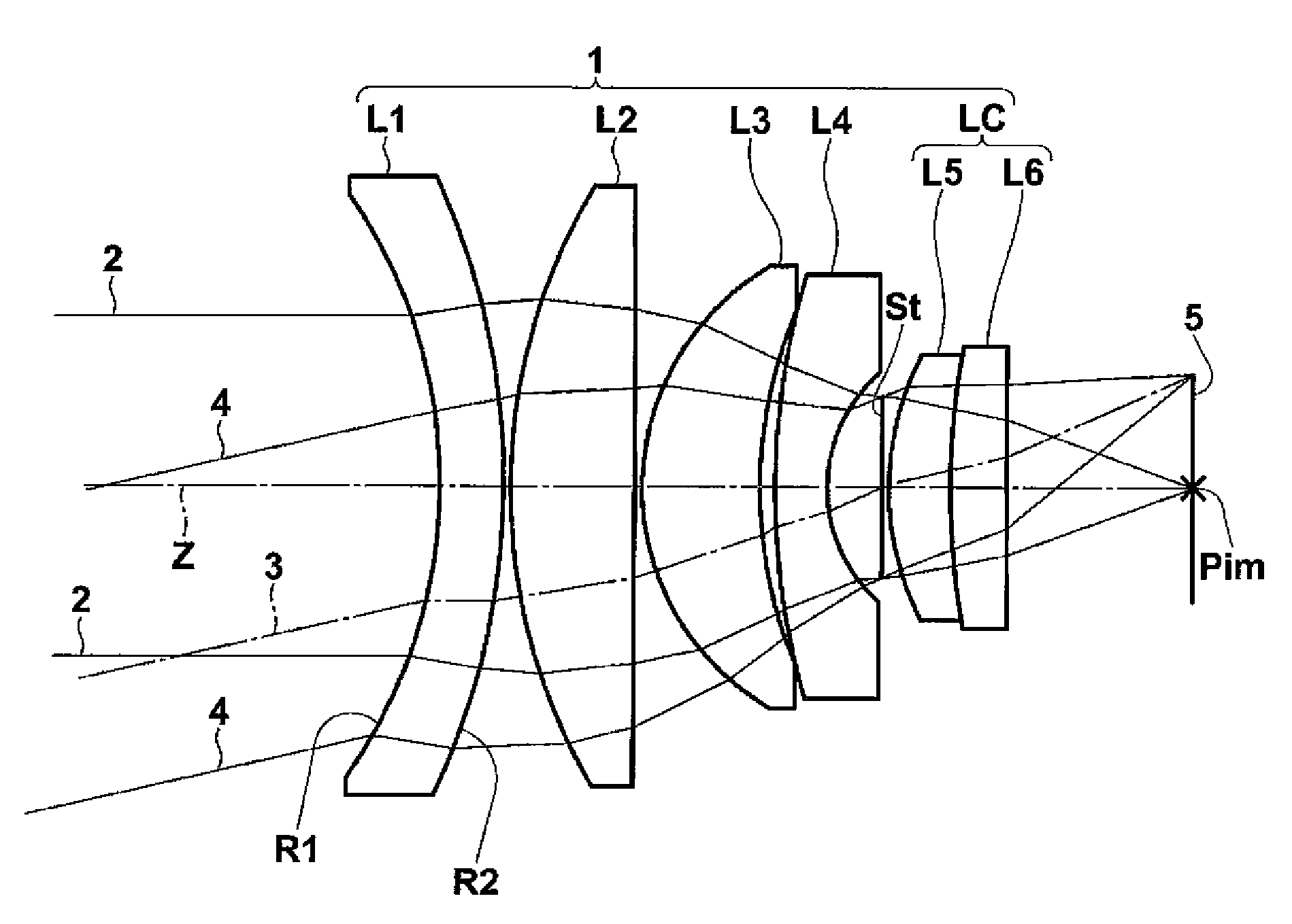
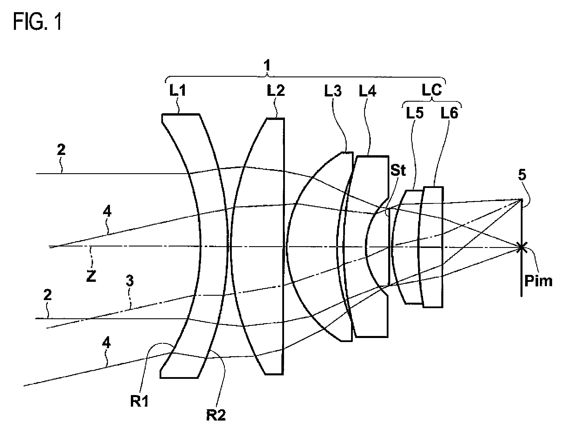
[0102]Hereinafter, numerical examples of the imaging lens system according to the embodiment of the invention will be described in detail. First, Example 1 will be described. FIG. 8 shows a lens configuration diagram of the imaging lens system according to the Example 1, and Table 1 shows lens data.

[0103]

TABLE 1Example 1 Lens DataSiRiDiNdjνdjSurfaceRadius ofSurfaceRefractiveAbbeNumbercurvatureseparationindexnumber1−14.4601.801.9228618.92−20.7380.20316.6393.501.8830040.84−2236.5060.2057.2463.301.8830040.8612.9270.44721.7771.451.9228618.984.3431.539 (AD*)∞0.2010 8.1881.731.7880047.411 22.1291.581.8051825.412 283.4125.24*AD: Aperture diaphragm

[0104]In the lens data of Table 1, a surface number Si represents the sequential number of i-th (i=1, 2, 3) surface that sequentially increases as it gets closer to the image side when a surface of a component on the most object side is defined as a first surface. In Table 1, Ri represents a radius of curvature of i-th surface, and Di represents a...


PUM


Abstract

The imaging lens system includes a negative first lens disposed on a most object side, having a concave surface directed toward the object side and having a meniscus shape, a cemented lens LC disposed on a most image side and having a convex surface on its most object side, and an aperture diaphragm disposed just in front of the object side of the cemented lens. The system satisfies the following conditional expressions:0.05<(R2−R1) / (R1+R2)<0.25vd1 −vd2 >15whereR1 and R2 denote radius of curvatures of object side and image side surfaces of the first lens, respectively, andvd1 and vd2 denote Abbe numbers of lenses, which are located on the most object side and on the most image side among lenses constituting the cemented lens, at the d-line, respectively.

Description

CROSS-REFERENCE TO RELATED APPLICATIONS[0001]This application is based upon and claims the benefit of priority from the Japanese Patent Application Nos. 2007-328236 and 2007-328237 both filed on Dec. 20, 2007; the entire contents of which are incorporated herein by reference.BACKGROUND OF THE INVENTION[0002]1. Technical Field[0003]The invention relates to an imaging lens system and an imaging apparatus, more particularly, to an imaging lens system suitable for use in a surveillance camera, a cell phone camera, an on-board camera, and the like employing an imaging device such as a CCD (Charge Coupled Device) and a CMOS (Complementary Metal Oxide Semiconductor), and an imaging apparatus having the imaging lens system.[0004]2. Description of the Related Art[0005]Recently, imaging devices such as CCD and CMOS have been downsized, and the number of pixels of the imaging device has been increased. In addition, an imaging apparatus main body having the imaging device has also been downsize...

Claims


Application Information

Patent Timeline
Patent Type & Authority Patents(United States)
IPC IPC(8): G02B9/60
CPCG02B13/146
Inventor KITAHARA, YU
Owner TIANJIN OFILM OPTO ELECTRONICS CO LTD
Why Eureka
Try Eureka