
Enclosure for electrical system

a technology for electrical systems and enclosures, applied in the direction of electrical apparatus casings/cabinets/drawers, furniture parts, instruments, etc., can solve the problems of increasing the noise escaping out of the computer system, and affecting the heat dissipation function

Inactive Publication Date: 2010-02-16
CLOUD NETWORK TECH SINGAPORE PTE LTD
View PDF22 Cites 42 Cited by
  • Summary
  • Abstract
  • Description
  • Claims
  • Application Information

AI Technical Summary

Benefits of technology

The patent describes an enclosure for an electrical system that has a movable part called an adjusting piece. This piece can cover certain parts of the system to help with heat dissipation. The main benefit of this design is that it allows for better control over the temperature of the system, which can help to improve its performance and reliability.

Problems solved by technology

In an electrical system, heat dissipation and noise suppression functions always hamper each other.
In a computer system for example, a plurality of heat dissipating holes are defined in the computer case to facilitate thermal control, an effective heat dissipating area can be increased by increasing a total number of the heat dissipating holes or a size of each heat dissipating hole, in order to enhance the heat dissipation, however, it will result in an increase of noise escaping out from the computer system; if we want to reduce the noise, the effective heat dissipating area can be reduced by reducing the total number of heat dissipating holes or the size of each heat dissipating hole, but it weakens effectiveness of the heat dissipation function.
It will be difficult to get an optimal balance between heat dissipation and noise suppression.

Method used


Image

  • Enclosure for electrical system
  • Enclosure for electrical system
  • Enclosure for electrical system

Examples


first embodiment

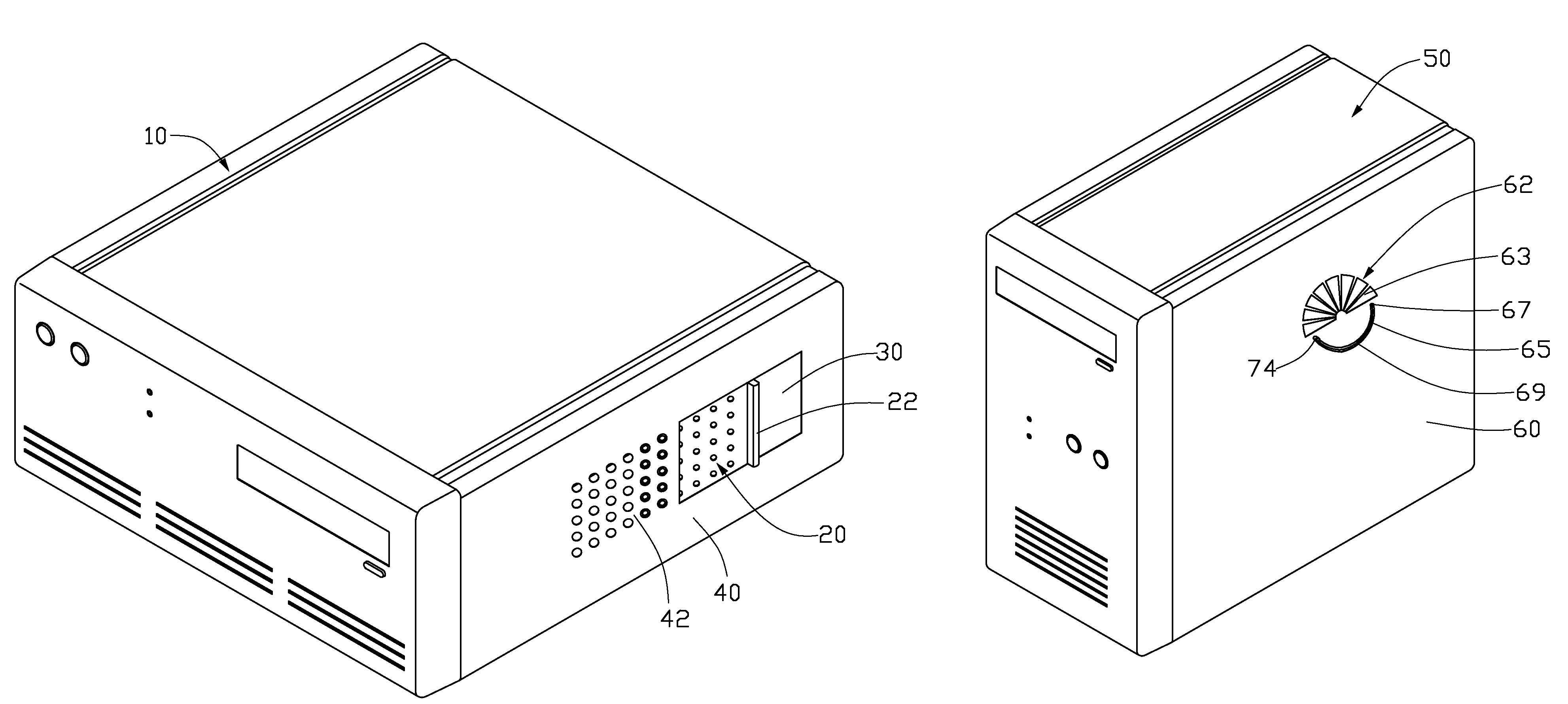
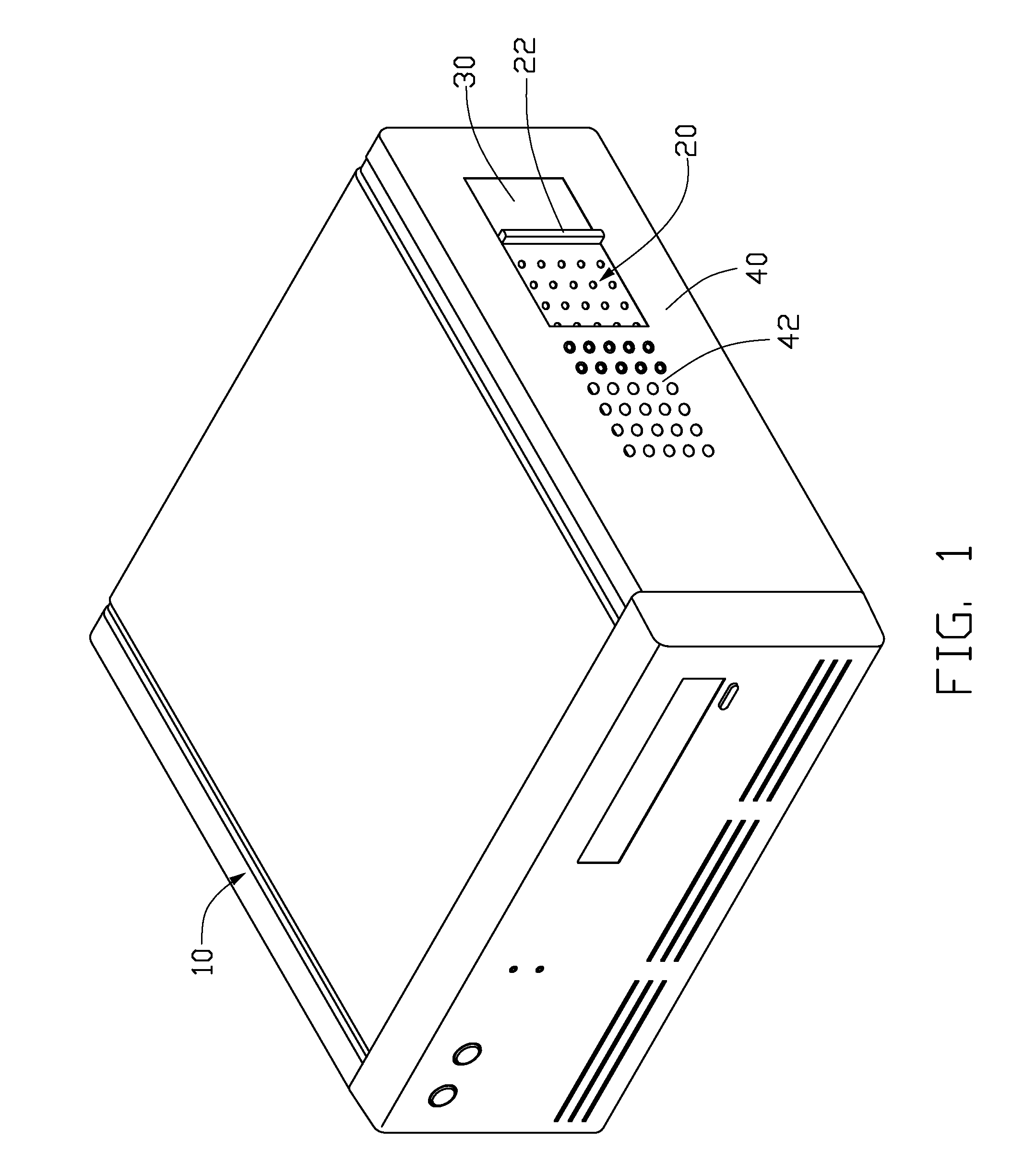
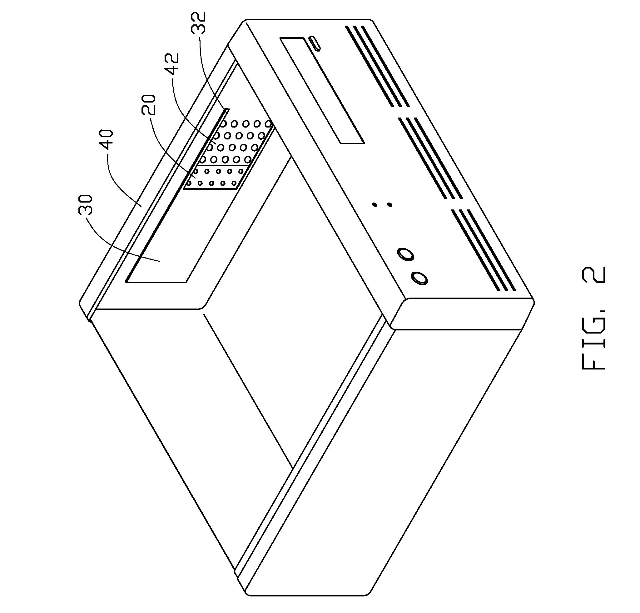
[0016]Referring to FIGS. 1 to 3, an enclosure for electrical system in accordance with the present invention is a computer case, which includes a chassis 10, an adjusting piece 20, and a cover board 30.

[0017]The chassis 10 includes a side plate 40. The side plate 40 includes a rectangular heat dissipating part 42 in which a plurality of uniformly arrayed heat dissipating holes 43 is defined, and a rectangular opening 44 defined adjacent to the dissipating part 42.

[0018]The adjusting piece 20 has a rectangular shape, its length is equal to a length of the opening 44 of the chassis 10, and its width is a little wider than a width of the opening 44. The adjusting piece 20 includes a plurality of heat dissipating holes 21 arrayed over a portion similar in size to the dissipating part 42 and in a similar manner as the heat dissipating holes 43, except that the heat dissipating holes 21 are smaller than the heat dissipating holes 43. A handle 22 is set at an end of the adjusting piece 20....

second embodiment

[0022]Referring to FIGS. 4 to 6, an enclosure in accordance with the present invention is a computer case, which includes a chassis 50, and an adjusting piece 70.

[0023]The chassis 50 includes a side plate 60. The side plate 60 includes a semicircular heat dissipating part 62, a pivot 64 protruding inwardly from an inner surface of the side plate 60, and an arcuate sliding slot 65 defined in the side plate 60. A plurality of uniformly arrayed heat dissipating holes 63 is radially defined in the heat dissipating part 62. The pivot 64 is set at a center of a semicircle comprised of the heat dissipating part 62 of the side plate 60. The sliding slot 65 is defined along a circumference of another semicircle whose center is also the center of the semicircle of the heat dissipating part 62. A rubber bushing 67 is received in the sliding slot 65. A slit 69 is defined in the rubber bushing 67 along the sliding slot 65.

[0024]The adjusting piece 70 is semicircular in shape. Its area is a littl...


PUM


Abstract

An enclosure for electrical system includes a side plate and an adjusting piece movably attached to the side plate. The side plate includes a heat dissipating part in which a plurality of heat dissipating holes is defined. The adjusting piece is movable with respect to the heat dissipating part for covering portions of at least some of the heat dissipating holes. The enclosure provides a function of adjusting of heat dissipation and noise suppression of an electrical system.

Description

BACKGROUND OF THE INVENTION[0001]1. Field of the Invention[0002]The present invention relates to enclosures for electrical systems, and particularly to a computer case with adjustable heat dissipation and noise suppression functions.[0003]2. Description of Related Art[0004]In an electrical system, heat dissipation and noise suppression functions always hamper each other.[0005]In a computer system for example, a plurality of heat dissipating holes are defined in the computer case to facilitate thermal control, an effective heat dissipating area can be increased by increasing a total number of the heat dissipating holes or a size of each heat dissipating hole, in order to enhance the heat dissipation, however, it will result in an increase of noise escaping out from the computer system; if we want to reduce the noise, the effective heat dissipating area can be reduced by reducing the total number of heat dissipating holes or the size of each heat dissipating hole, but it weakens effec...

Claims


Application Information

Patent Timeline
Patent Type & Authority Patents(United States)
IPC IPC(8): H05K7/20H05K5/00
CPCG06F1/20H05K7/20127
Inventor KUO, SZU-WEI
Owner CLOUD NETWORK TECH SINGAPORE PTE LTD
Learn More