[0022]
Thermal control is also enhanced relative to microreaction devices employing parallel numbering up (or even employing a single unitary mixer) because the serial configuration of the present invention inevitably results in a lower adiabatic temperature rise (or decrease) than even the most finely divided parallel reaction design. This is because the energy produced (or consumed) by the reaction at a given one of the mixers in the devices of the present type is spread throughout a greater
mass of fluid than in a parallel numbered-up reactor or unitary reactor, since the entire primary passage reactant
stream is present at every reaction point. Assuming equal flows and
thermal mass flows in the principal and secondary passages, for example, and equal division of flows out from four exits the secondary passage, the baseline adiabatic temperature change at the first confluence or first mixer location (where the total
mass flow is the least) in devices of the present invention is only ⅖ of the adiabatic temperature change of an equal-splitting parallel mixer architecture. If the total
thermal mass flow is greater in the principal passage than in the secondary passage, the
advantage of the present invention only increases. For example, where the ratio of
thermal mass flow rates of the principal passage to the secondary passage is 2:1, the adiabatic temperature change in a device of the present invention having four exits from the secondary passage is only ⅓ that of a parallel or unitary mixer, at the first mixing or confluence point.
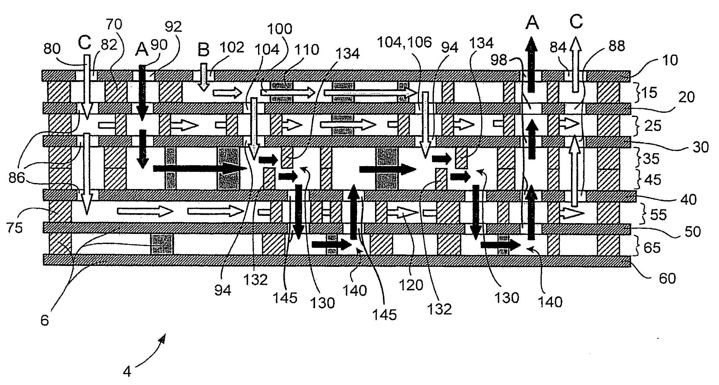
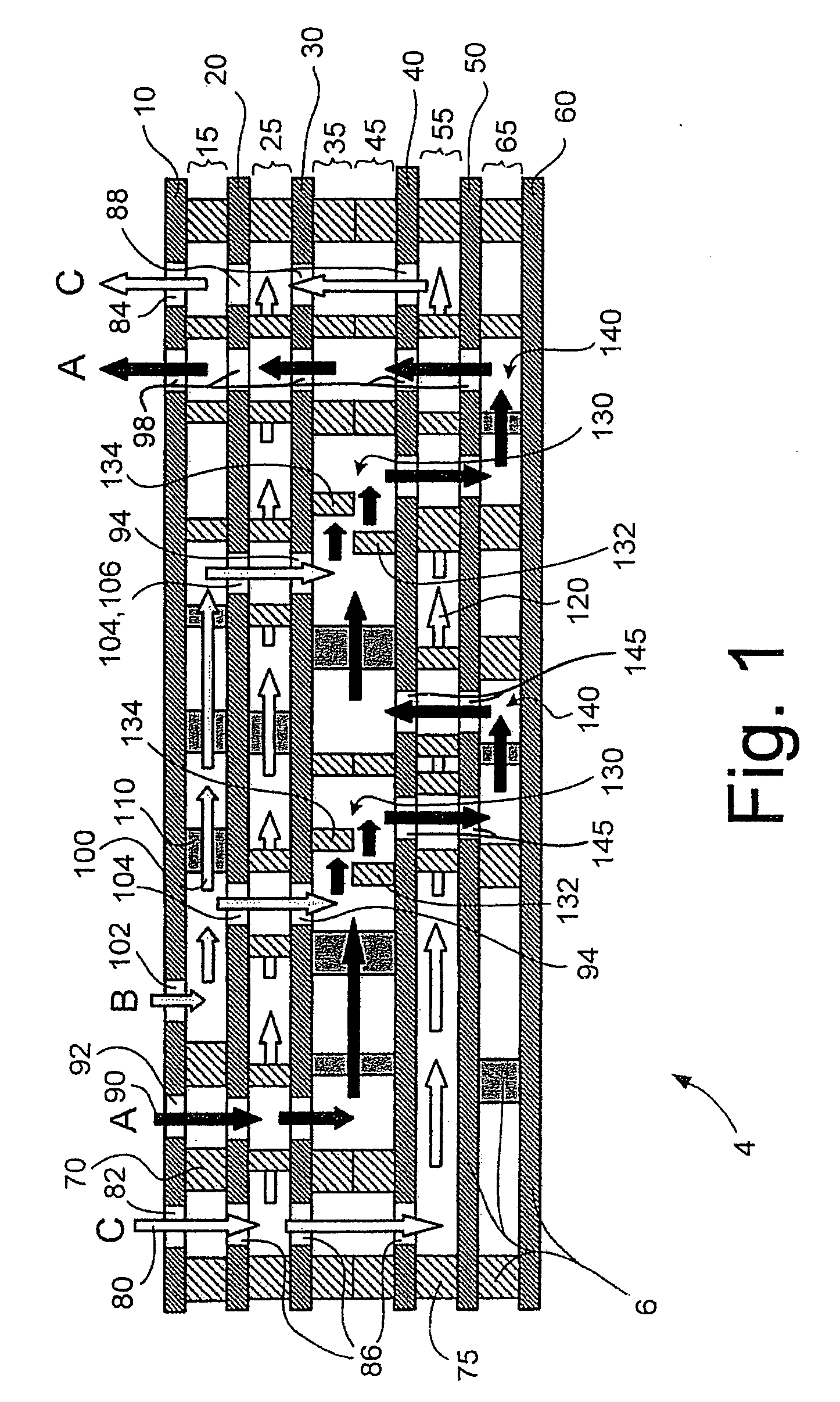
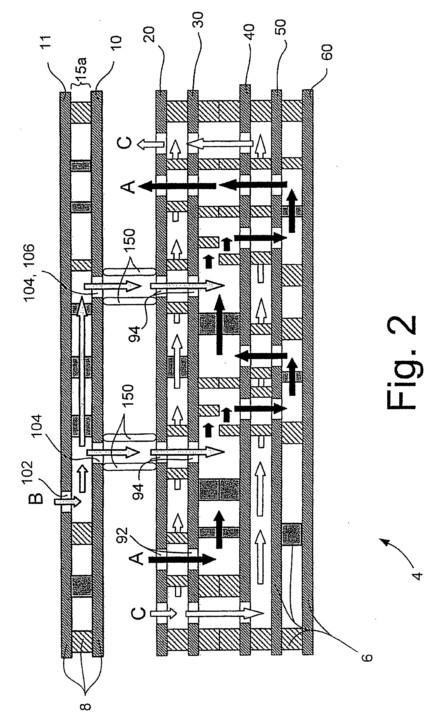
[0023]According to the invention, flow splitting for separate flow distribution is employed only in one or more secondary fluidic passages, but not in the principal fluidic passage. Further, the flow splitting in the secondary fluidic passage is of a different type than in traditional microreactors with internal (or external) numbering up. Instead of many parallel flows at equal pressures and flow rates, successive serial splits or exits from the secondary fluid passage at different pressures are used. Passage features, such as sub-passage lengths, which vary along the passage from one exit to the next, are used to provide lower pressure at each successive exit. The pressure drop thus induced matches the pressure drop of the fluid in the associated principal fluidic passage, thus guaranteeing that fluid in the principal fluidic passage does not leave that passage, and that mixing and / or reaction processes take place essentially all in the principal fluidic passage and essentially not in the secondary fluidic passage.
[0024]The successive serial mixing or dosing of one reactant into another provided by the present invention also improves local molar ratio control over previous
microreactor architectures of similar throughput capability. Because the secondary passage reactant is introduced in small amounts relative to the total flow, the secondary passage reactant is effectively dosed into the principal passage reactant and the possibility is minimized of any buildup of localized excess amounts of that reactant.
[0025]Further, in contrast to the typical parallel-numbering-up schemes in previous microreaction devices, any flow imbalance that may exist or arise in the devices of the present invention between the various split flows of the secondary passage are not performance-critical. The parallel nature of previous devices results in the need for flow splitting of both or all incoming reactant streams, such that imbalance in one reactant passage typically results directly in over-molar-ratio conditions at least one location in the microreaction device. One such imbalance can also compound with another, so that very small imbalances may have very large effects, particularly in more sensitive reactions.
[0026]In the present invention, in contrast, for the large number of reactions which are well-behaved with molar ratios of one or more reactants at or below a
target level, the proper conditions for a well-behaved reaction can generally be readily maintained regardless of any flow variations in the secondary fluidic passage. As long as the pressure balances are appropriate to confine the reactant
stream entering the principal passage to that passage, and as long as the flows at the primary entrances are at the desired molar ratio or even tilted toward the well-behaved side, any imbalance in flow rates from the secondary passage into the principal passage cannot cause unfavorable over-molar-ratio conditions. The result is stable, reliable, repeatable reaction performance.
[0027]If the secondary fluidic passage is provided within a secondary unitary body, as according to one of the alternative embodiments of the present invention, multiple alternate secondary unitary bodies may be supplied as a part of the inventive device or system. The secondary fluidic passages of at least some of the multiple alternate secondary unitary bodies can vary in one or more physical parameters from those of one or more others of the secondary unitary bodies, such that proper pressure balancing can be maintained over a wide range of reactant or
working fluid types and flows by switching out one secondary fluidic passage for another. This avoids both the expense of multiple precision pumps on the one hand, and the expense of a microreaction device with internal flow splitting optimized only for a single reaction or
reaction type on the other hand. Instead, a simple external component can be provided in several interchangeable types to
handle serial flow splitting and
pressure management for a wide range of reactant or
working fluid types and flow rates. Where highest flexibility over varying operating conditions is required, however, multiple pumps or other variable external control may of course be the most desirable and most economical solution.

