Splitting type spatial multi-branch distribution heat pipe and preparation method thereof

A technology of branch tubes and multi-branches, which is applied in the splicing space multi-branch heat pipe and its manufacturing field, can solve the problems of poor flexibility of production methods, difficulty in mass production, and large sintering space, so as to save processing space and heat dissipation space , good thermal control, the effect of solving heat dissipation problems

Active Publication Date: 2017-03-08
SOUTH CHINA UNIV OF TECH
View PDF6 Cites 12 Cited by
  • Summary
  • Abstract
  • Description
  • Claims
  • Application Information

AI Technical Summary

Problems solved by technology

The fixed structure occupies a large sintering space, and in order to adapt to different heat dissipation environments, multiple sets of mandrels are required to cooperate with sintering after changing the structure. The flexibility of the production method is poor, and it is difficult to produce in large quantities.

Method used


Image

  • Splitting type spatial multi-branch distribution heat pipe and preparation method thereof
  • Splitting type spatial multi-branch distribution heat pipe and preparation method thereof
  • Splitting type spatial multi-branch distribution heat pipe and preparation method thereof

Examples


Embodiment 1

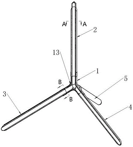
[0061] The above-mentioned space multi-channel pipe joints are prepared as four joints, and each shell is a circular spliced ​​space multi-branch distributed heat pipe:

[0062] (1) The sintered mandrel that will be prepared for molding, including the first sintered mandrel 6, the second sintered mandrel 9 and the third sintered mandrel 10; the graphite sleeve for fixing, including the first graphite sleeve 7, the second The second graphite sleeve 8 and the third graphite sleeve 11; derusting and degreasing the space multi-channel joint 1, each sintered mandrel and each shell;

[0063] The diameter of the first sintered mandrel 6 is smaller than the inner diameter of each shell, and the length is longer than the length of each shell; the diameters of the second sintered mandrel 9 and the third sintered mandrel 10 are smaller than the sealed type of the space four-channel pipe joint 1 The inner diameter and length of the cavity are greater than the length of each channel, and o...

Embodiment 2

[0070] The above-mentioned space multi-channel pipe joints are prepared as four joints, and each shell is a circular spliced ​​space multi-branch distributed heat pipe:

[0071] (1) The sintered mandrel that will be prepared for molding, including the first sintered mandrel 6, the second sintered mandrel 9 and the third sintered mandrel 10; the graphite sleeve for fixing, including the first graphite sleeve 7, the second The second graphite sleeve 8 and the third graphite sleeve 11; derusting and degreasing the space multi-channel joint 1, each sintered mandrel and each shell;

[0072] The diameter of the first sintered mandrel 6 is smaller than the inner diameter of each shell, and the length is longer than the length of each shell; the diameters of the second sintered mandrel 9 and the third sintered mandrel 10 are smaller than the sealed type of the space four-channel pipe joint 1 The inner diameter and length of the cavity are greater than the length of each channel, and o...

Embodiment 3

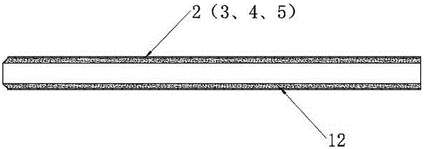
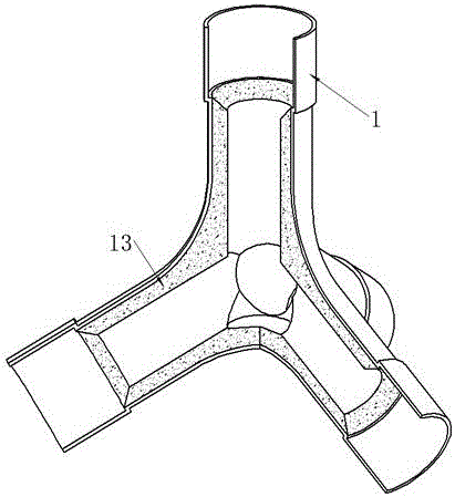
[0079] Similar to embodiment 2, the difference is that the chamfers on the first graphite sleeve 7 and the third graphite sleeve 11 are 60°, and the copper metal powder of the capillary layer in each tube shell is 75 mesh, with more space The sealed cavity of the channel pipe joint 1 is filled with 125-mesh copper metal powder, the sintering temperature is 850°C, the sintering time is 2 hours, the porosity of the porous capillary joint 13 and the porous capillary layer 12 is 70% and 60%, The vacuum is 15Pa. Other conditions remain unchanged, and a multi-branch distributed heat pipe with spliced ​​tetrahedral support space with similar performance can also be obtained.


PUM


Abstract

The invention discloses a splitting type spatial multi-branch distribution heat pipe and a preparation method thereof. The splitting type spatial multi-branch distribution heat pipe comprises a spatial multi-channel pipe joint (1), a first branch pipe housing (2), a second branch pipe housing (3), a third branch pipe housing (4) and a fourth branch pipe housing (5). According to the splitting type spatial multi-branch distribution heat pipe, a spatial connecting type sintering multi-pore capillary layer is arranged inside, so that the heat transfer performance is outstanding; meanwhile, the angle of each port of the spatial multi-channel joint can be selected in advance, so as to flexibly change the bifurcation shape of the spatial multi-branch pipe to meet different heat dissipating space requirements, and a flexible, reliable and stable heat dissipating environment is provided to the miniaturized multi-chip integral development of electronic equipment; branches and joints are separately manufactured and then split during the preparation process, so that the manufacturing is simple, the cost is low, and the industrial production demand is met.

Description

technical field [0001] The invention relates to a heat pipe and a manufacturing method thereof, in particular to a spliced ​​space multi-branch heat pipe and a manufacturing method thereof. Background technique [0002] The traditional heat pipe is mainly composed of a closed single metal tube shell, the capillary structure of the inner wall of the tube shell and the liquid working medium filled in the metal tube shell, and a certain degree of vacuum is maintained in the metal tube shell to improve the start-up of the heat pipe. ability. The working principle of the heat pipe is: a heat source is installed at the evaporation end of the heat pipe, and the liquid working medium in the pipe body is vaporized by absorbing the heat emitted by the heat source, and the generated steam flows to the condensation end of the heat pipe driven by the difference in steam pressure, and the steam flows at the condensation end. Liquefaction condenses into a liquid and releases latent heat. ...

Claims


Application Information

Patent Timeline
Patent Type & Authority Applications(China)
IPC IPC(8): F28D15/04
CPCF28D15/0266F28F9/26F28D15/046F28D2021/0029
Inventor 汤勇钟桂生蔡杨华李宗涛梁观伟庄宝山万珍平
Owner SOUTH CHINA UNIV OF TECH
Why Eureka
Try Eureka