A spliced space multi-branch distribution heat pipe and its preparation method
A technology of branch tubes and multi-branches, which is applied in the splicing space multi-branch heat pipe and its manufacturing field, can solve the problems of poor flexibility of production methods, difficulty in mass production, and large sintering space, so as to save processing space and heat dissipation space , good heat control, and the effect of solving heat dissipation problems
- Summary
- Abstract
- Description
- Claims
- Application Information
AI Technical Summary
Problems solved by technology
Method used
Image
Examples
Embodiment 1
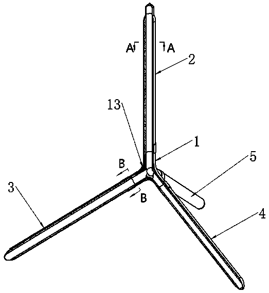
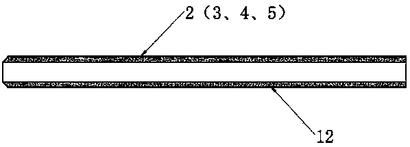
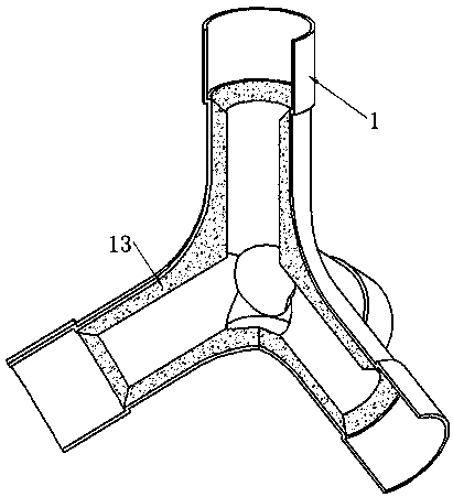
[0061] The above-mentioned space multi-channel pipe joints are prepared as four joints, and each shell is a circular spliced space multi-branch distributed heat pipe:
[0062] (1) The sintered mandrel that will be prepared for molding includes the first sintered mandrel 6, the second sintered mandrel 9 and the third sintered mandrel 10; the graphite cover for fixing includes the first graphite cover 7, the second sintered mandrel The second graphite sleeve 8 and the third graphite sleeve 11; derusting and degreasing the space multi-channel joint 1, each sintered mandrel and each shell;
[0063] The diameter of the first sintered mandrel 6 is smaller than the inner diameter of each shell, and the length is longer than the length of each shell; the diameters of the second sintered mandrel 9 and the third sintered mandrel 10 are smaller than the sealed type of the space four-channel pipe joint 1 The inner diameter of cavity, length are greater than each channel length, and one ...
Embodiment 2
[0070] The above-mentioned space multi-channel pipe joints are prepared as four joints, and each shell is a circular spliced space multi-branch distributed heat pipe:
[0071] (1) The sintered mandrel that will be prepared for molding includes the first sintered mandrel 6, the second sintered mandrel 9 and the third sintered mandrel 10; the graphite cover for fixing includes the first graphite cover 7, the second sintered mandrel The second graphite sleeve 8 and the third graphite sleeve 11; derusting and degreasing the space multi-channel joint 1, each sintered mandrel and each shell;
[0072] The diameter of the first sintered mandrel 6 is smaller than the inner diameter of each shell, and the length is longer than the length of each shell; the diameters of the second sintered mandrel 9 and the third sintered mandrel 10 are smaller than the sealed type of the space four-channel pipe joint 1 The inner diameter of cavity, length are greater than each channel length, and one ...
Embodiment 3
[0079] Similar to embodiment 2, the difference is that the chamfers on the first graphite sleeve 7 and the third graphite sleeve 11 are 60°, and the copper metal powder of the capillary layer in each tube shell is 75 mesh, with more space The sealed cavity of the channel pipe joint 1 is filled with 125-mesh copper metal powder, the sintering temperature is 850°C, the sintering time is 2 hours, the porosity of the porous capillary joint 13 and the porous capillary layer 12 is 70% and 60%, The vacuum is 15Pa. Other conditions remain unchanged, and a multi-branch distributed heat pipe with spliced tetrahedral support space with similar performance can also be obtained.
PUM
 Abstract
Description
Claims
Application Information
 - R&D
- Intellectual Property
- Life Sciences
- Materials
- Tech Scout
- Unparalleled Data Quality
- Higher Quality Content
- 60% Fewer Hallucinations
Browse by: Latest US Patents, China's latest patents, Technical Efficacy Thesaurus, Application Domain, Technology Topic, Popular Technical Reports.
© 2025 PatSnap. All rights reserved.Legal|Privacy policy|Modern Slavery Act Transparency Statement|Sitemap|About US| Contact US: help@patsnap.com


