Floor hole repair method

a technology for floor holes and fixing fixtures, which is applied in the field of floor hole repair fixtures and methods, can solve the problems of frequent undesired depressions or defects in flooring materials, and the lack of fire barrier that is often required in the floor hole repair system,

Active Publication Date: 2010-02-23
REEN MICHAEL J
View PDF60 Cites 33 Cited by
  • Summary
  • Abstract
  • Description
  • Claims
  • Application Information

AI Technical Summary

Benefits of technology

[0006]In a first aspect of the invention, a method for repairing a hole in a floor includes the steps of (a) providing a floor hole repair fixture defining an inner volume and having a depending rim; (b) connecting the fixture to at least one side surface of the hole; and (c) substantially or completely filling the inner volume of the fixture with grout. The method may further include the step of (d) seating the fixture within the hole so that the depending rim seats over a portion of flooring surface adjacent to the hole. Where such rim is so seated, it may be affixed to the portion of the flooring surface with one or more fasteners. Fasteners may also be used to connect the fixture to the at least one side surface of the hole. The method may further include the steps of (e) applying a skim coat over the upper rim of the fixture and over a portion of flooring surface adjacent to the hole; and (f) installing a flooring material over at least the rim of the floor hole repair fixture. To better meet fire and safety codes, preferably at least a portion of the outer surface of the fixture is coated with an intumescent coating, either at the factory or before the fixture is installed within the hole.
[0007]In a second aspect of the invention, a floor hole repair fixture has at least one side wall; a rim depending from the side wall; a bottom, wherein the at least one side wall and bottom define an inner volume to hold a grout material when such fixture is installed inside a floor hole. Preferably, the fixture has a bottom wall and a vertical side wall that is generally cylindrically shaped. The vertical side wall and bottom wall define an inner generally cylindrical volume to hold a grout material. The rim may depend from the upper portion of the side wall and form a ring. An intumescent coating may be applied to or formed on an outer surface of the at least one side wall and on an outer surface of the bottom. In one embodiment, the at least one side wall, rim and bottom of the fixture are formed integrally from high strength material, such as metal, preferably steel. To make it easier to install the floor hole repair fixture within a hole in a floor deck, such as a concrete floor deck, one or more holes may be preformed in the sidewall and in the rim. Such holes are adapted to receive fasteners for joining the floor hole repair fixture to the floor deck.

Problems solved by technology

Such floor hole repair system frequently leads to undesired depressions or defects in the flooring material due to settling or shrinking of the grout 16 and / or due to movement of the plate 10.
Such floor hole repair system lacks a fire barrier often required by building codes and fire prevention regulations applicable to commercial buildings.

Method used


Image

  • Floor hole repair method
  • Floor hole repair method
  • Floor hole repair method

Examples


Embodiment Construction

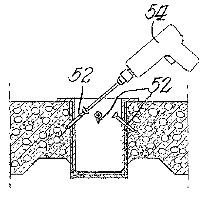
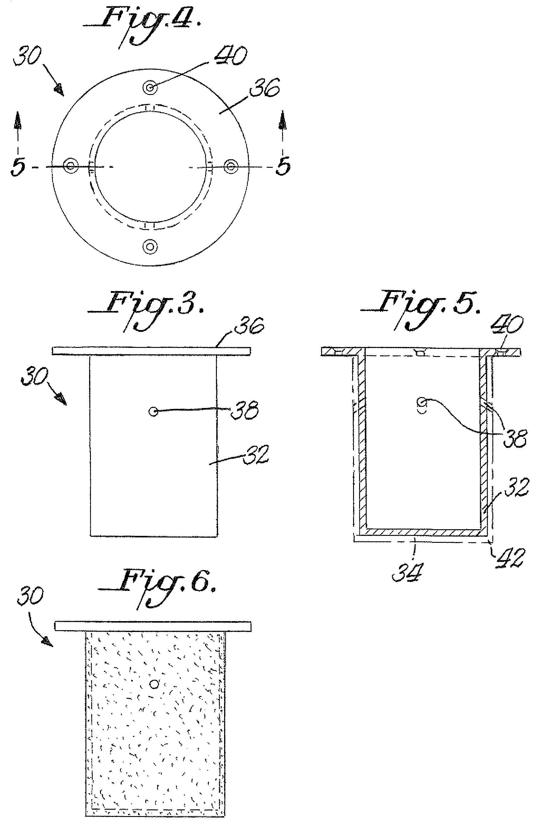
[0019]Referring to FIGS. 3-6, a floor hole repair fixture 30 according to an embodiment of the invention has a sidewall 32 defining a generally cylindrical volume and a bottom wall 34. The bottom wall 34 in the embodiment shown in FIG. 4 has a generally circular shape with a diameter. The diameter of the bottom wall 34 may be provided in different sizes to accommodate repairs to different size holes in deck flooring. One suitable size range for the bottom wall diameter is from 2 inches to 6 inches, preferably in the range from 2.75 inches to 5.75 inches. The sidewall has a height that is comparable to the thickness of the flooring deck in the floor to be repaired. A suitable sidewall height can be, for example, about 4 inches.

[0020]A generally circular rim 36 or flange depends from the upper portion of the sidewall 32. The rim 32 has a generally flat upper surface and a generally flat bottom surface. As such, the floor hole repair fixture 30 somewhat resembles an upside-down top hat...


PUM

PropertyMeasurementUnit
diameteraaaaaaaaaa
diameteraaaaaaaaaa
heightaaaaaaaaaa

Abstract

A floor hole repair fixture has at least one vertical side wall and a bottom wall which together define an inner volume. The fixture is connected to a hole in a floor with one or more fasteners and is filled with a non-shrink grout. A depending rim or flange extending from the at least one side wall helps seat the fixture within the hole. Intumescent material may be coated onto or applied to external fixture surfaces before the fixture is inserted into the hole. Floor covering material is installed over the grout-filled fixture.

Description

FIELD OF THE INVENTION[0001]This invention relates to a floor hole repair fixture and method with particular advantage for commercial or industrial buildings having an elevated concrete deck floor.BACKGROUND OF THE INVENTION[0002]Many commercial buildings with multiple stories have concrete deck floor support for each floor above ground level. Holes may be formed through such deck floor support to permit passage of conduit for cables or piping installed to supply various utility and information technology services throughout the commercial building. Building codes and fire regulations require use of certain insulation, barriers and intumescent coatings to retard the spread of fire from one floor to another.[0003]When the building owner or occupant / tenant desires to change a floor layout, such that cables and piping or conduit are relocated from one location to another, an open hole or core hole through the concrete deck forming the floor may be left that previously was occupied by c...

Claims


Application Information

Patent Timeline
Patent Type & Authority Patents(United States)
IPC IPC(8): E04B1/00
CPCE04G23/0203Y10T29/49732Y10T29/49718
Inventor REEN, MICHAEL J.
Owner REEN MICHAEL J
Why Eureka
Try Eureka