Secondary fuel delivery system

a fuel delivery system and fuel delivery technology, applied in the ignition of turbine/propulsion engines, engine starters, lighting and heating apparatus, etc., can solve the problems of increased production of unwanted emissions, excessive wear, and inability to achieve balanced results, so as to avoid heat dissipation difficulties and reduce the impact of elevated vibration levels

Active Publication Date: 2010-02-23
SIEMENS ENERGY INC
View PDF39 Cites 67 Cited by
  • Summary
  • Abstract
  • Description
  • Claims
  • Application Information

AI Technical Summary

Benefits of technology

[0009]This arrangement advantageously delivers a secondary fuel / diluent mixture to a secondary combustion zone located along the length of the transition piece, while reducing the impact of elevated vibration levels found within the transition piece and avoiding the heat dissipation difficulties often associated with traditional vibration reduction methods.

Problems solved by technology

One challenge in such single site injection systems is there is always a balance to be obtained between the combustion temperature and the efficiency of the combustor.
However, while increasing the combustion temperature can produce increased energy levels, it can also have negative results, including increased production of unwanted emissions, such as oxides of nitrogen (NOx), for which overall levels are directly related to the length of time spent at elevated temperatures.
The transition piece can, for example, be a difficult place in which to mount a secondary fuel delivery system, because it is prone to especially-high levels of vibration, and placing known secondary fuel delivery systems there will subject them to forces which, if not addressed, can lead to excessive wear and can cause premature failure.
Use of traditional vibration reduction methods, such as increasing component mass to improve stiffness, present additional difficulties when applied to the transition section, because the additional bulk is not only difficult to cool, but it can also interfere with the delicate aerodynamic characteristics of the flow path, leading to overall losses in efficiency and / or performance issues.

Method used


Image

  • Secondary fuel delivery system
  • Secondary fuel delivery system
  • Secondary fuel delivery system

Examples


Embodiment Construction

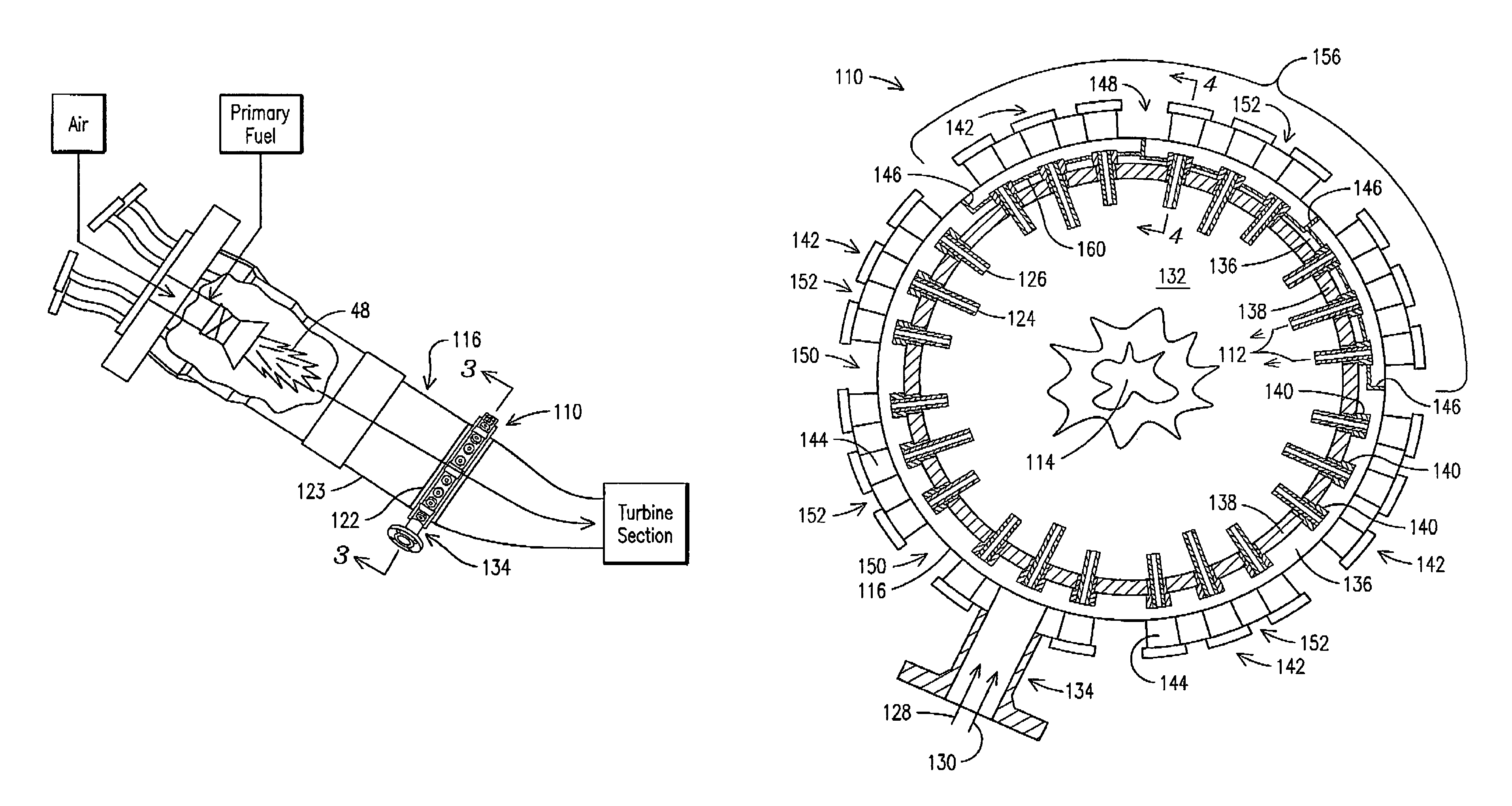
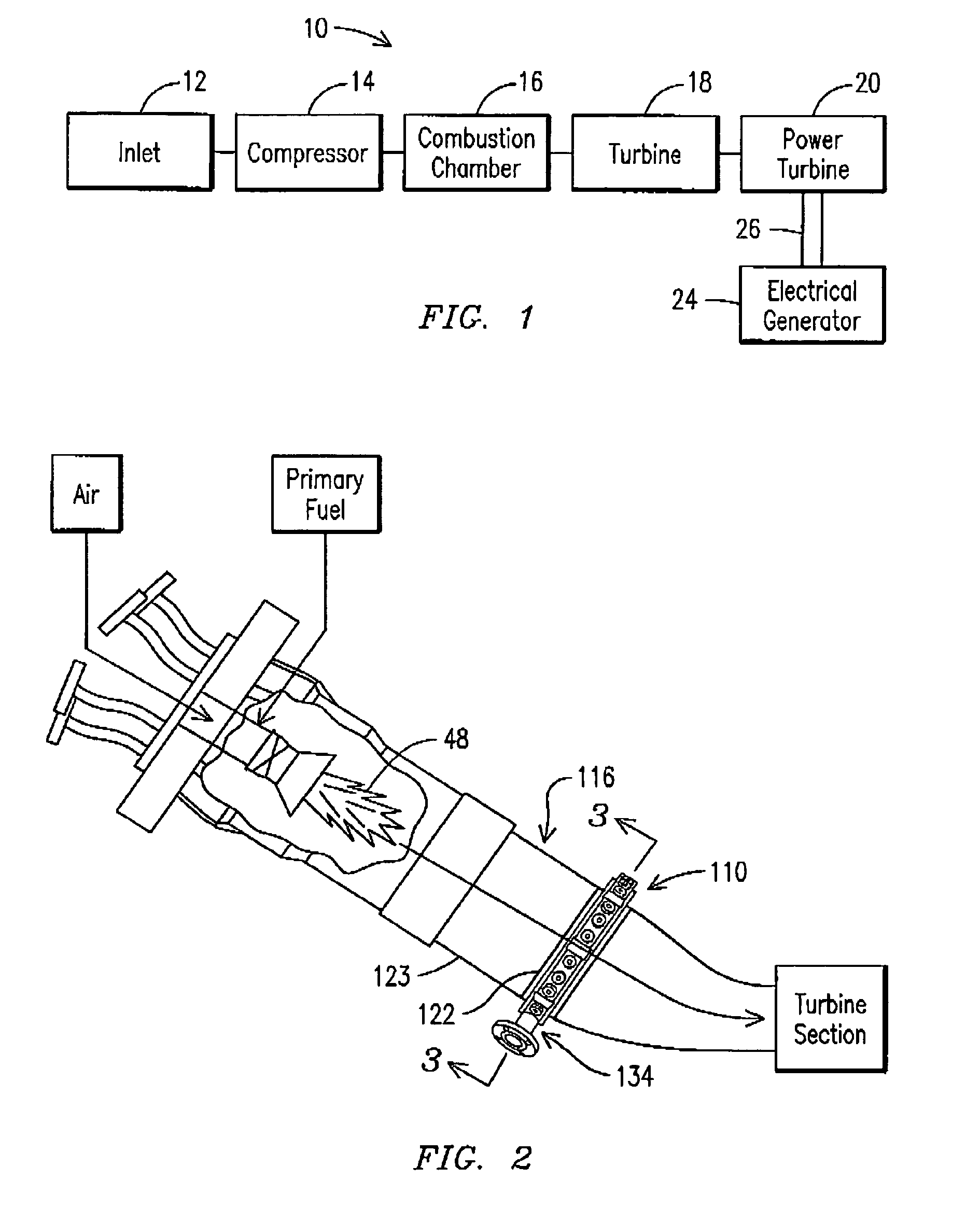
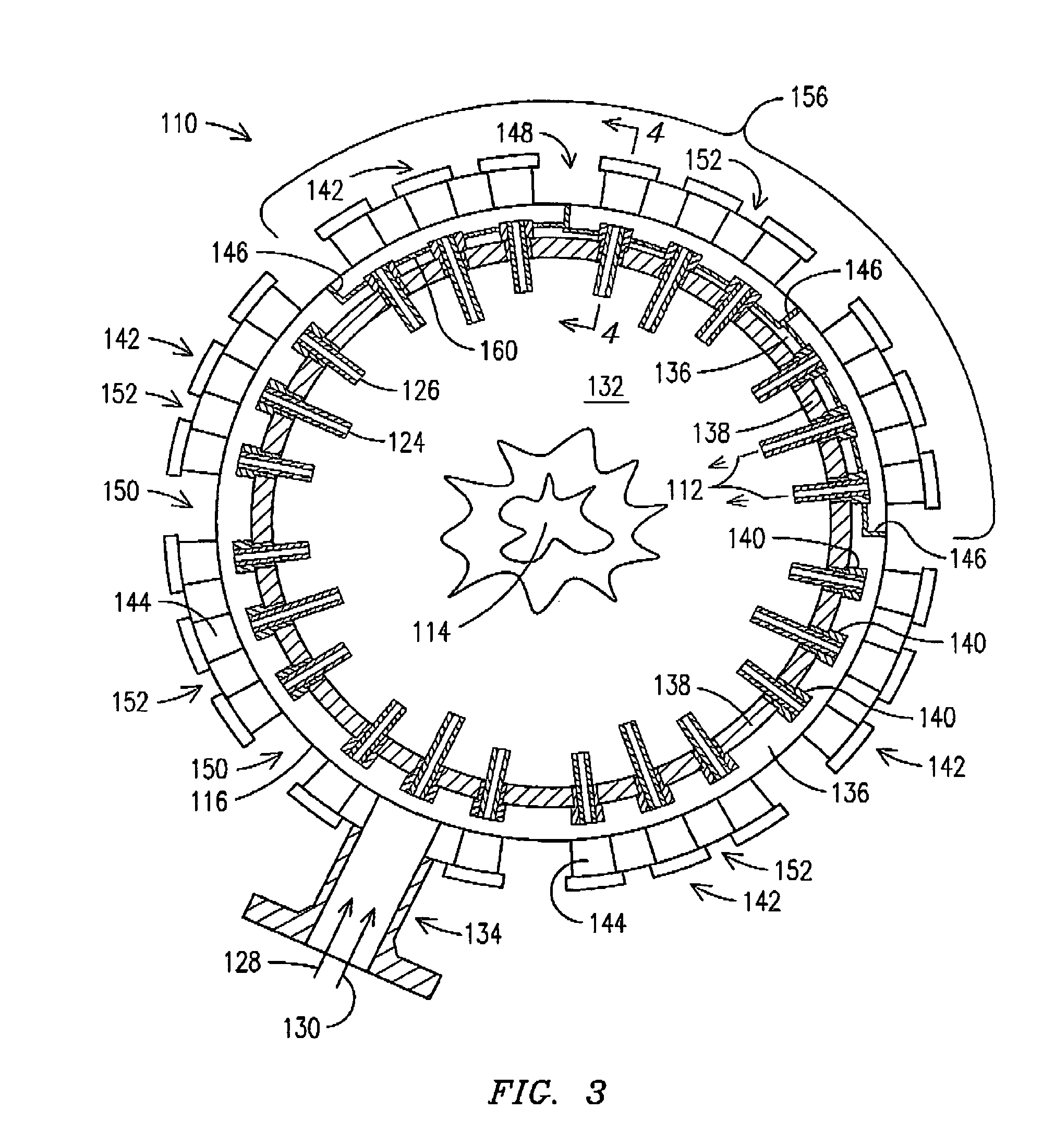
[0017]Reference is now made in general to the figures, wherein the secondary fuel delivery system 110 of the present invention is shown. As shown in FIGS. 2, 3, and 4, the fuel delivery system 110 is especially-suited for providing a secondary stream 112 of fuel and / or diluent to a secondary combustion zone 114, located within the transition piece 116, downstream of the primary combustion zone 48, as a way of, among other things, reducing NOx emissions levels during operation of the associated turbine engine, not shown. By way of overview, and with additional reference to FIG. 3, the secondary fuel delivery system 110 includes a manifold 122 disposed circumferentially around the transition piece 116, a manifold inlet port 134 through which a secondary supply of fuel 128 and / or diluent 130 enters the manifold main cavity 136, and a plurality of long and short injector nozzles 124, 126 for distributing fuel and / or diluent into a secondary combustion zone 114 located in the interior re...


PUM


Abstract

A secondary fuel delivery system for delivering a secondary stream of fuel and / or diluent to a secondary combustion zone located in the transition piece of a combustion engine, downstream of the engine primary combustion region is disclosed. The system includes a manifold formed integral to, and surrounding a portion of, the transition piece, a manifold inlet port, and a collection of injection nozzles. A flowsleeve augments fuel / diluent flow velocity and improves the system cooling effectiveness. Passive cooling elements, including effusion cooling holes located within the transition boundary and thermal-stress-dissipating gaps that resist thermal stress accumulation, provide supplemental heat dissipation in key areas. The system delivers a secondary fuel / diluent mixture to a secondary combustion zone located along the length of the transition piece, while reducing the impact of elevated vibration levels found within the transition piece and avoiding the heat dissipation difficulties often associated with traditional vibration reduction methods.

Description

CROSS-REFERENCE TO RELATED APPLICATIONS[0001]This invention claims priority to U.S. Provisional application 60 / 972,405 filed on Sep. 14, 2007 entitled, “Fuel Manifold for Axially Staged Combustion System”. This invention is also a Continuation in Part of US application entitled, “Apparatus and Method for Controlling the Secondary Injection of Fuel”, filed on Aug. 20, 2008 and having a Ser. No. 12 / 194,611, which, in turn, claims priority to U.S. Provisional application 60 / 972,395 entitled, “Apparatus and Method for Controlling the Secondary Injection of Fuel.” Each of these above-mentioned applications is herein incorporated by reference.STATEMENT REGARDING FEDERALLY SPONSORED DEVELOPMENT[0002]Development for this invention was supported in part by Contract No. DE-FC26-05NT42644, awarded by the United States Department of Energy. Accordingly, the United States Government may have certain rights in this invention.FIELD OF THE INVENTION[0003]This invention relates generally to the fiel...

Claims


Application Information

Patent Timeline
Patent Type & Authority Patents(United States)
IPC IPC(8): F02C7/26
CPCF23R3/28F23R3/346F23R3/36
Inventor PARKER, DAVID M.CAI, WEIDONGGARAN, DANIEL W.HARRIS, ARTHUR J.
Owner SIEMENS ENERGY INC
Why Eureka
Try Eureka