Methods for manufacturing porous nuclear fuel elements for high-temperature gas-cooled nuclear reactors

a technology of high-temperature gas-cooled nuclear reactors and nuclear fuel elements, which is applied in the field of porous nuclear fuel elements, can solve the problems of limiting maneuverability and destinations, chemical systems will not be able to extend human space exploration much beyond, and the potential for lowering thrust, etc., and achieves high melting temperatures, high thermal conductivity, and high resistance to erosion.

Inactive Publication Date: 2010-02-23
NAT TECH & ENG SOLUTIONS OF SANDIA LLC
View PDF8 Cites 32 Cited by
  • Summary
  • Abstract
  • Description
  • Claims
  • Application Information

AI Technical Summary

Problems solved by technology

The primary problem is that even advanced chemical rocket systems limit maneuverability and destinations.
Chemical systems will not be able to extend human space exploration much beyond the moon or Mars.
Such designs clearly have potential for lower thrust, long-Isp NEP systems, but are limited by their maximum operating temperature when high-thrust, shorter-pulse NTP systems or bimodal NTP / NEP systems would best meet mission requirements.
Current designs for high-temperature gas-cooled reactor fuel elements, such as annual rods or pebble beds, cannot operate at extremely high temperatures and, thus, have limited efficiency.
However, the uranium bi-carbide fuels were never infiltrated into a porous matrix structure to make a porous fuel element.
In addition, single-phase, solid-solution uranium tri-carbide fuels, such as (U,Zr,Nb)C, were never seriously considered because they had not been synthesized or fabricated at that point in time.
Unfortunately, the method of fabrication described above for producing these advanced uranium tri-carbide fuels (i.e., liquid-phase sintering), cannot be used to deposit thin coatings of nuclear fuel onto exposed interior surfaces of a highly porous foam skeleton made of, e.g., reticulated vitreous or glassy carbon.
The sintering step would quickly destroy the thin, interconnected structural ligaments.
Therefore, the previous process of liquid-phase sintering cannot be used to make a porous, gas-permeable fuel element made of uranium tri-carbide fuel.

Method used


Image

  • Methods for manufacturing porous nuclear fuel elements for high-temperature gas-cooled nuclear reactors
  • Methods for manufacturing porous nuclear fuel elements for high-temperature gas-cooled nuclear reactors
  • Methods for manufacturing porous nuclear fuel elements for high-temperature gas-cooled nuclear reactors

Examples


Embodiment Construction

[0042]Herein, when we refer to a tri-carbide nuclear fuel, e.g., (U,Zr,Nb)C, we broadly define this to include hyper- and hypo-stoichimetric compositions, such as (U0.1 Zr0.77 Nb0.13) C0.95, in addition to stoichimetric compositions. Additionally, when we refer to uranium, we broadly define this as including any fissile element, including enriched uranium, americium, plutonium, and mixtures thereof, unless otherwise specifically stated.

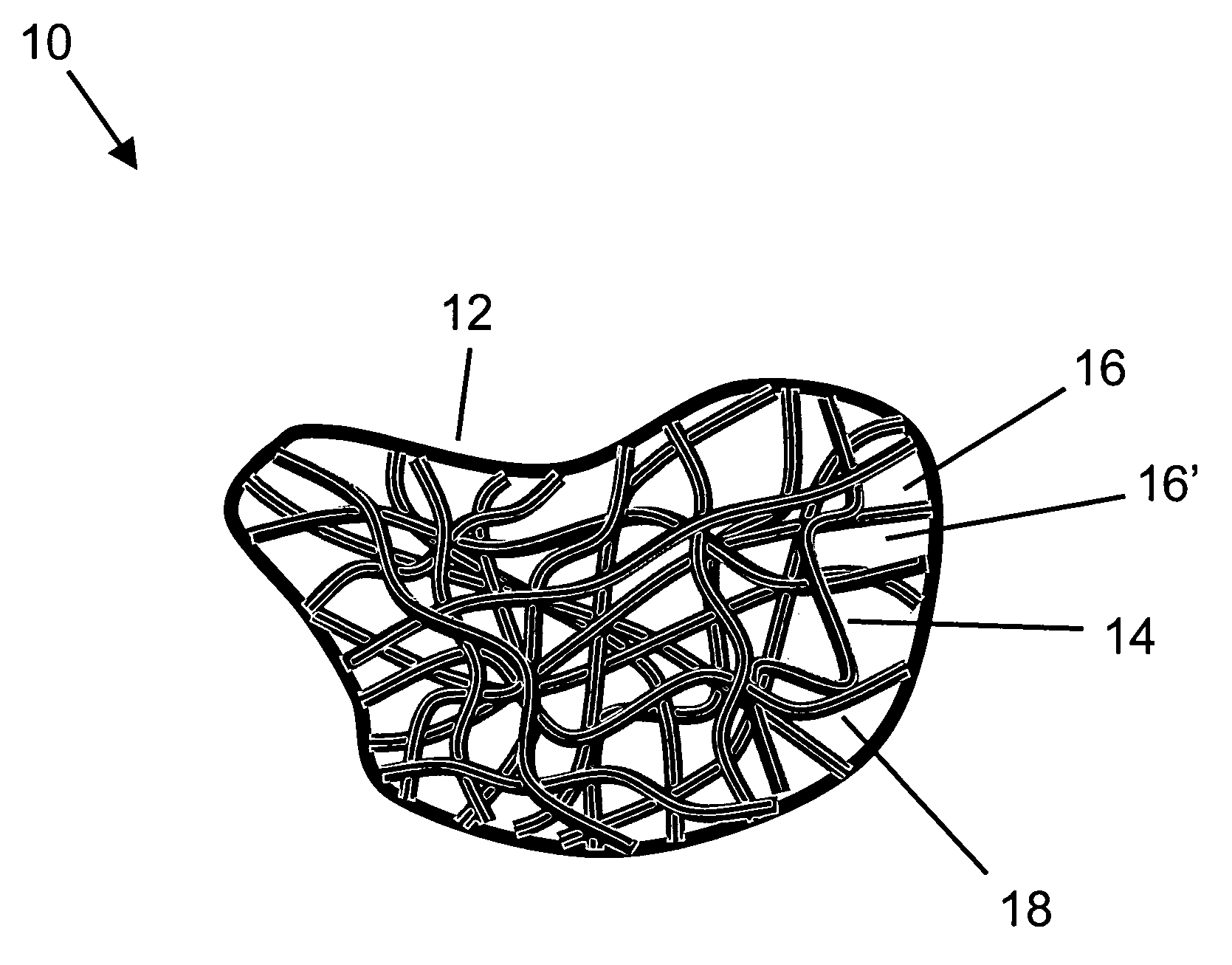
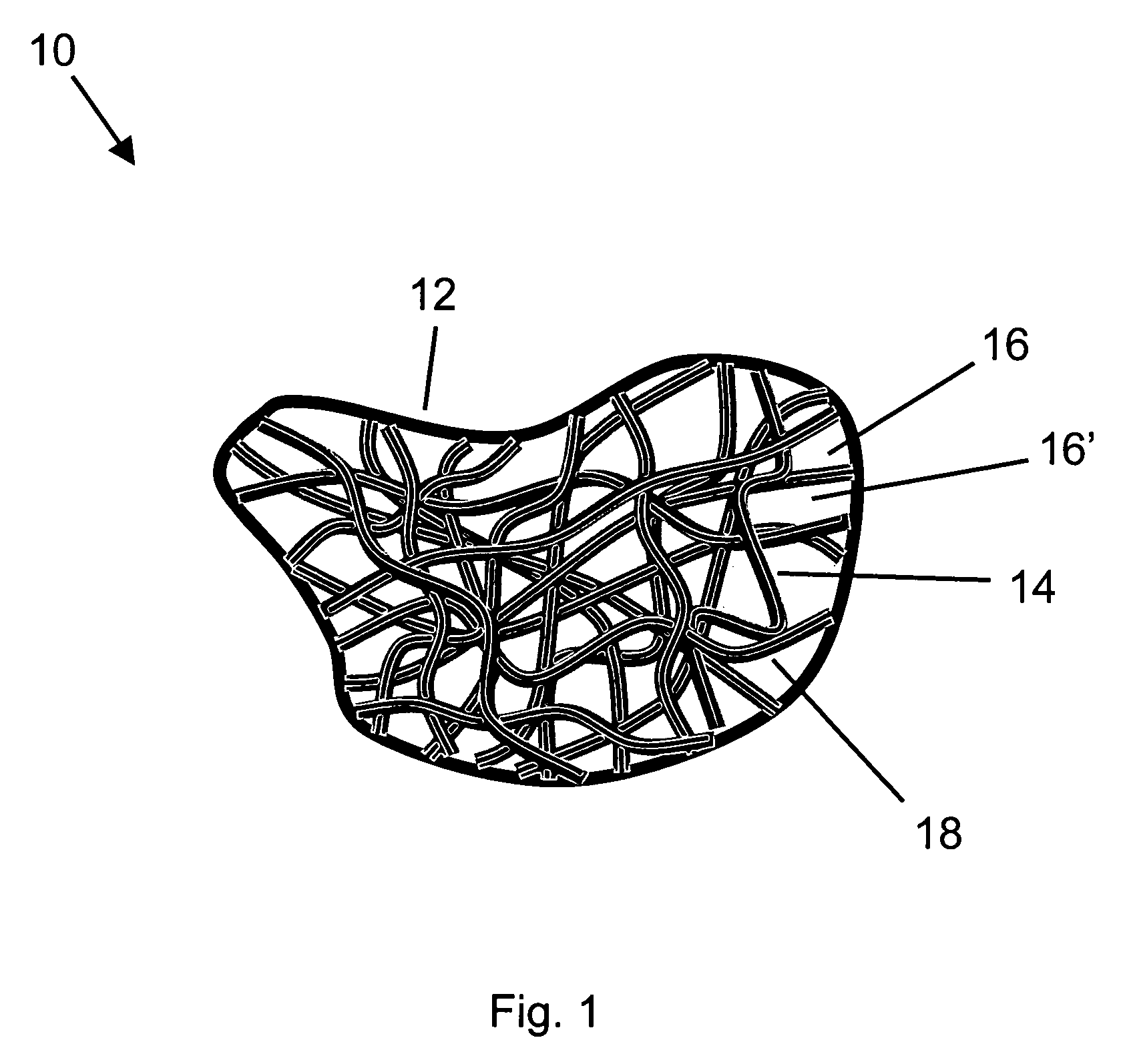
[0043]FIG. 1 illustrates a schematic side view of an example of a porous nuclear fuel element, according to the present invention. Fuel element 10 comprises a porous body 12 comprising internal structure 14 and interconnected pores 16, 16′, etc. In this example, internal structure 14 is illustrated as a fibrous body comprising a tangled web or woven mesh of fibers or ligaments. Nuclear fuel 18 is disposed on the external surfaces of internal structure 14. Fuel 18 comprises one or more alloys selected from the group consisting of solid solution uranium...


PUM

PropertyMeasurementUnit
total porosityaaaaaaaaaa
porosityaaaaaaaaaa

Abstract

Methods for manufacturing porous nuclear fuel elements for use in advanced high temperature gas-cooled nuclear reactors (HTGR's). Advanced uranium bi-carbide, uranium tri-carbide and uranium carbonitride nuclear fuels can be used. These fuels have high melting temperatures, high thermal conductivity, and high resistance to erosion by hot hydrogen gas. Tri-carbide fuels, such as (U,Zr,Nb)C, can be fabricated using chemical vapor infiltration (CVI) to simultaneously deposit each of the three separate carbides, e.g., UC, ZrC, and NbC in a single CVI step. By using CVI, a thin coating of nuclear fuel may be deposited inside of a highly porous skeletal structure made, for example, of reticulated vitreous carbon foam.

Description

CROSS-REFERENCE TO RELATED APPLICATIONS[0001]This application is a divisional application of U.S. Se. No. 10 / 881,873, Porous Nuclear Fuel Element for High-Temperature Gas Cooled Nuclear Reactors, Youchison et al., filed Jun. 29, 2004, which is incorporated herein by reference.FEDERALLY SPONSORED RESEARCH[0002]The United States Government has rights in this invention pursuant to Department of Energy Contract No. DE-AC04-94AL85000 with Sandia Corporation.BACKGROUND OF THE INVENTION[0003]The present invention relates generally to porous nuclear fuel elements for use in advanced high temperature gas-cooled nuclear reactors (HTGR's), and to methods for fabricating same.[0004]Exploring the solar system while maintaining reasonable interplanetary travel times will require increases in spacecraft velocities of one to two orders of magnitude over currently achievable levels. The “packaged energy” for space propulsion systems required to achieve this goal, expressed as a combination of specif...

Claims


Application Information

Patent Timeline
Patent Type & Authority Patents(United States)
IPC IPC(8): A61M36/14B05D3/02C23C16/00G21C3/06
CPCG21C3/58G21C21/02Y02E30/38Y02E30/33Y02E30/30
Inventor YOUCHISON, DENNIS L.WILLIAMS, BRIAN E.BENANDER, ROBERT E.
Owner NAT TECH & ENG SOLUTIONS OF SANDIA LLC
Why Eureka
Try Eureka