Power switching apparatus with open-load detection

a technology of power switching apparatus and detection device, which is applied in the direction of emergency protective arrangement for limiting excess voltage/current, emergency protection arrangement for limiting excess current, etc., which can solve the problem of not being able to detect open-load during the on-state of the switch, generating unacceptable visible light, and introducing not only additional cost and space requirements, circuits also introduce additional voltage drop

Active Publication Date: 2010-02-23
CONTI TEMIC MICROELECTRONIC GMBH +1
View PDF17 Cites 15 Cited by
  • Summary
  • Abstract
  • Description
  • Claims
  • Application Information

AI Technical Summary

Problems solved by technology

The disadvantage of this solution is that it is not acceptable for detection of open-load during the ON-state of the switch, which is a particular disadvantage in many applications, such as switching automotive lighting, for example incandescent bulbs or light-emitting diodes (‘LED’s).
Even measurement during the OFF-state of the load can only be performed when the output is energised at least at low current levels but which may also generate unacceptable visible light, especially when using LED light sources.
However, such circuits introduce not only additional cost and space requirements but also an additional voltage drop.
This common and effective solution suffers mainly from a poor precision of the circuit recopy at small output currents.
When the voltage drop across the switch is of the same magnitude as the offset of the regulating amplifier the error of the circuit can exceed 100% and adequate current measurement is no more possible.
In the case of a standard driver used to drive a wide spread of loads this minimum current becomes difficult to measure.
Measuring 100 mA on a minimum Rdson of 20 mOhm (during ON state) means an absolute signal of 2 mV to be measured in a harsh environment (fast transients on supply), which is simply not a realistic solution in most applications of this kind.

Method used


Image

  • Power switching apparatus with open-load detection
  • Power switching apparatus with open-load detection
  • Power switching apparatus with open-load detection

Examples


Embodiment Construction

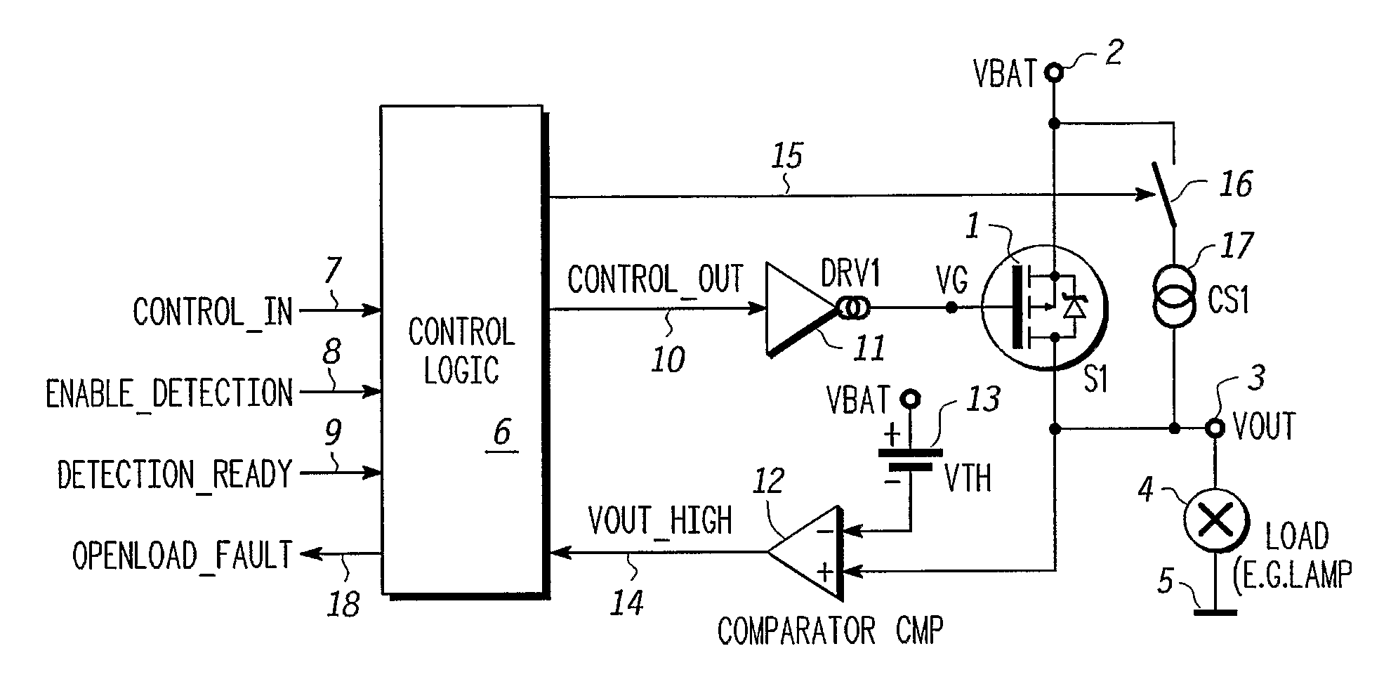
[0018]The power switching apparatus shown in FIG. 1 comprises a switch 1 in the form of a MOSFET (metal-oxide field-effect transistor) controlled by a control voltage VG applied to a gate and a drain and source connected respectively to output terminals 2 and 3. In use, the output terminals 2 and 3 are connected in series between a power supply (not shown), applying a voltage Vbat to the terminal 2, and a load 4 connected between the output terminal 3 and ground 5. This embodiment of the invention is particularly applicable to automotive equipment and will be described with reference to such an application, notably where the load consists of one or more lamps, such as an incandescent bulb or LED (light-emitting diode) and the power supply is a DC voltage provided by an accumulator and alternator. However it will be appreciated that the invention may also be used in other applications.

[0019]The apparatus comprises a control logic unit 6 that receives a Control_in signal at an input 7...


PUM


Abstract

Power switching apparatus comprising switch means having a control terminal and output terminals for connection in series between a power supply and a load. The switch means is responsive to a control signal applied to the control terminal to switch between an ON-state in which it supplies power supply current from the power supply through the output terminals to the load and an OFF-state in which it interrupts the supply of power through the output terminals to the load. The apparatus includes detection means for detecting an open-load condition of the load at least during the ON-state of the switch means, comprising detection control means operable in the ON-state of the switch means for modifying the control signal so as to start switching the switch means to the OFF-state during a lapse of time substantially less than the time required for the switch means to reach the OFF-state and for restoring the control signal to a value corresponding to the ON-state at or before the end of the lapse of time, and comparator means responsive to variation of voltage at the output terminals during the lapse of time. The duration of the variation of voltage during the open-load detection is too short and its magnitude too small for the variation of load current to be perceptible, notably in the case where the load is a lamp.

Description

FIELD OF THE INVENTION[0001]This invention relates to power switching apparatus with open-load detection and more particularly with capability for detecting an open-load condition in the ON-state.BACKGROUND OF THE INVENTION[0002]Power switching apparatus with open-load detection, referred to as a ‘smart power switch’, is used in many applications, including automotive equipment, especially to control vehicle lighting, for example. The present invention is particularly, but not exclusively, usable in such applications.[0003]Integrated smart power switches use different strategies to detect the disconnection of an output load.[0004]The simplest strategy is to monitor the status of the output during the OFF-state. In a known system of this kind, a very small test current is fed to the output line and the voltage across the load is monitored by a voltage comparator. With a normal load, the low impedance of the load ties the output voltage close to ground level (in the case of a high-sid...

Claims


Application Information

Patent Timeline
Patent Type & Authority Patents(United States)
IPC IPC(8): H02H3/08
CPCH02H3/12
Inventor TURPIN, PIERREGUILLOTT, LAURENTHEMON, ERWANJOOS, ULISCHNELL, JOSEF
Owner CONTI TEMIC MICROELECTRONIC GMBH
Why Eureka
Try Eureka