Sheet presser and image scanner

a sheet presser and scanner technology, applied in the direction of electrographic processes, instruments, printing, etc., can solve the problems of low degree of processing or dimensional accuracy, uneven contact increase the possibility of occurrence of the clearance between the pressing member and the scanning surface, so as to improve the sharpness

Active Publication Date: 2010-03-02
BROTHER KOGYO KK
View PDF11 Cites 2 Cited by
  • Summary
  • Abstract
  • Description
  • Claims
  • Application Information

AI Technical Summary

Benefits of technology

[0009]In particular, in a case where the pressing member is configured such that a distance from a point where the pressing member is attached to the main body of the machine to a position where the pressing member and the scanning surface are in contact with each other is made short for reducing the required cost, elastic deformability of the pressing member is lowered, thereby further increasing a possibility of occurrence of the clearance between the pressing member and the scanning surface.
[0016]Further, in the present sheet presser, each of the pivot shaft portions is basically held pressed onto the remote end (away from the sheet) of the bearing bore which is long in the directions perpendicular to the sheet, thereby preventing the pressing member from moving toward the sheet. Therefore, the acute angle formed between the predetermined direction in which the sheet is conveyed and the pressing member is held within the predetermined range (e.g., 2.5°-5°). Accordingly, there is maintained a clearance between the sheet and the pressing member at a scanning position (shown in FIG. 6) where an image on the sheet is scanned, thereby eliminating an inconvenience that foreign matters accumulate at the scanning position, which would be otherwise caused.
[0019]In the above sheet presser according to the second form, since the pressing member has the at least one cutout in the vicinity of each bearing bore, a rigidity of the pressing member around the cutout can be reduced.
[0025]To keep the close contact between the pressing surface and the supporting surface where the potential positional error is expected to be too large for relatively small-sized bearing bores or clearances therein to keep the dose contact, the size of the bores should be increased, to avoid an excessive force being imposed on the supporting surface or the sheet presser. However, this enlarging the bearing bores is not desirable, in view of instability and others which would be caused by such arrangement. The provision of the deformable portion according to the third preferable mode is effective for avoiding this undesirable enlargement of the bore size, since the deformable portion cooperates with the clearances defined in the bearing bores to keep the close contact between the supporting surface and the pressing surface, eliminating the necessity of enlarging the bores.
[0027]The image scanner according to the second aspect is equipped with the sheet presser according to any one of the first through third forms of the first aspect of the invention which has a pressing member which is uniformly held in contact with the sheet. Hence, the target surface of the sheet can be uniformly pressed onto the scanning device, with no clearance between the scanning device and the target surface in any part in the width direction, i.e., in the direction perpendicular to the conveyance direction. Thus, the present image scanner is capable of scanning an image on the target surface with enhanced sharpness.

Problems solved by technology

However, the pressing member may suffer from uneven contact with the scanning surface due to low degrees of processing or dimensional accuracy and positional accuracy of the pressing member.
In particular, in a case where the pressing member is configured such that a distance from a point where the pressing member is attached to the main body of the machine to a position where the pressing member and the scanning surface are in contact with each other is made short for reducing the required cost, elastic deformability of the pressing member is lowered, thereby further increasing a possibility of occurrence of the clearance between the pressing member and the scanning surface.

Method used


Image

  • Sheet presser and image scanner
  • Sheet presser and image scanner
  • Sheet presser and image scanner

Examples


first embodiment

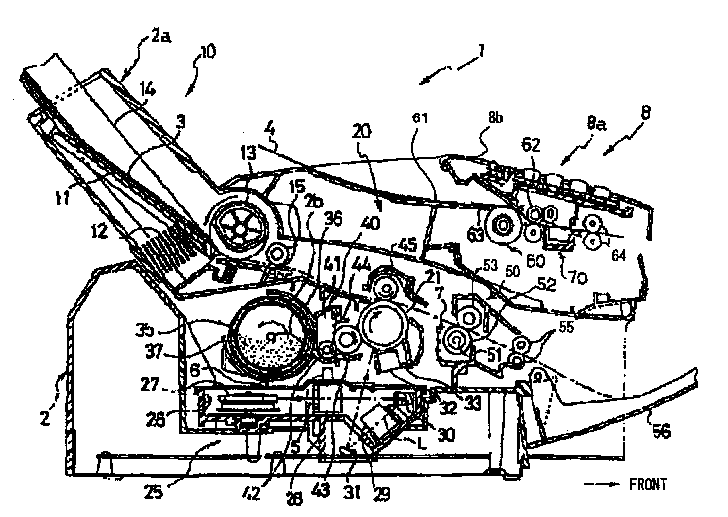
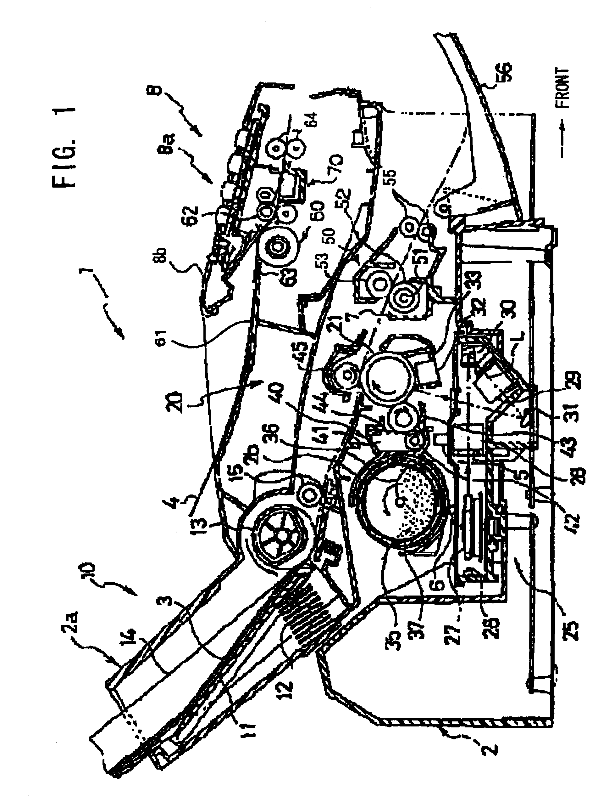
[0039]A sheet presser and an image scanner according to the invention is installed in a multifunction apparatus equipped with multiple functions such as a print function, copy function, scanner function, facsimile function and telephone function.

[0040]FIG. 1 is a schematic diagram of the multifunction apparatus 1 which has a housing 2 incorporating a feeder unit 10, a laser scanner unit 25, a laser printer 20 having a photoconductive drum 21, an image scanner 70, a drive mechanism (not shown) for driving relevant components including the photoconductive drum 21 and various rollers, and a control unit (not shown) for controlling the multifunction apparatus 1.

[0041]The feeder unit 10 is composed such that a sheet holding plate 11 is disposed in a feeder case 2a which is disposed on the upper side of a rear portion of the housing 2, as shown in FIG. 1, with a front side end of the sheet holding plate 11 elastically biased upward by a compression spring 12. In the feeder unit 10, there ...

second embodiment

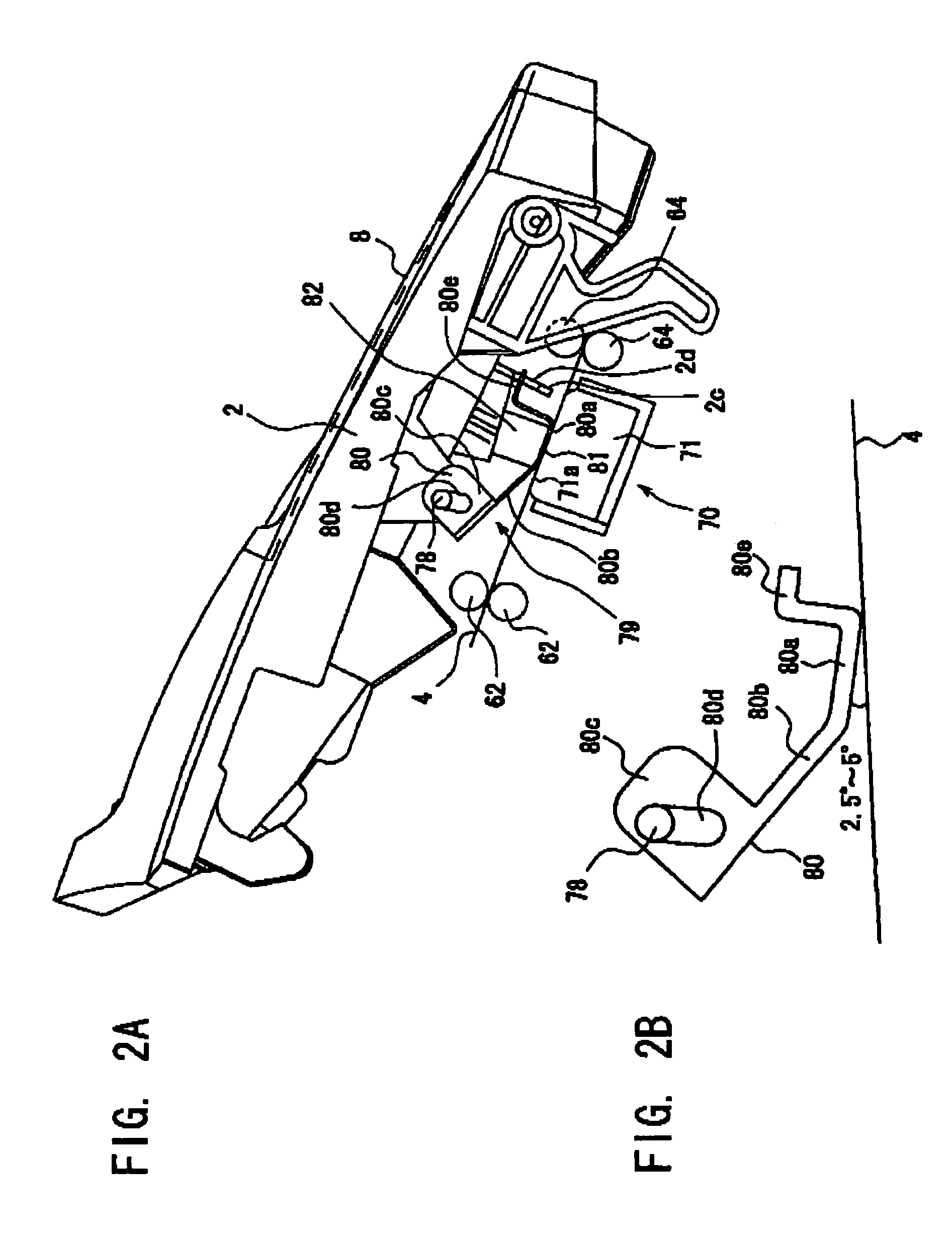
[0094] a shape of each bearing bore 80d (bearing one of the pivot shafts 78) of the sheet presser 79 is a perfect circle having a diameter corresponding to the diameter of the pivot shaft 78 and the sheet presser 80 is not able to move relative to the pivot shafts 78.

[0095]In the sheet presser 79 according to the second embodiment, a pair of slits 83 are formed in the vicinity of a boundary between the planar portion 80a and the slant portion 80b of the pressing member 80, as, shown in FIG. 7. Each of the slit 83 extend in a direction perpendicular to the sheet conveyance direction from one of lateral ends of the pressing member 80 toward the center thereof, and thus a narrow portion 84 is formed between the slits 83. The pressing member 80 can be easily twisted at the narrow portion 84 around an axis extending in the sheet conveyance direction.

[0096]Accordingly, even where the pressing member 80 is tilted as a whole with respect to the scanning surface 71a as seen from the sheet co...

third embodiment

[0099]In the sheet presser 79 two slits 83 are formed such that the slits 83 extend parallel to each other from an end of the slant portion 80b of the pressing member 80 in the sheet conveyance direction into the planar portion 80a, as shown in FIG. 9

[0100]The provision of the slits 83 reduces the rigidity of the pressing member 80, making the pressing member 80 easy to be twisted around an axis extending in the sheet conveyance direction.

[0101]Thus, even where the pressing member 80 as a whole is tilted with respect to the scanning surface 71a as seen in the sheet conveyance direction, the planar portion 80a pressed by the coil spring 82 toward the scanning surface 71a can be easily twisted and become parallel to the scanning surface 71a.

[0102]According to the third embodiment, even where the pressing member 80 as a whole has not been parallel to the scanning surface 71a, the planar portion 80a is always uniformly brought into contact with the scanning surface 71a and the sheet 4...


PUM


Abstract

A sheet presser including two pivot shaft portions fixedly disposed substantially coaxially with each other and parallel to a sheet of a document conveyed in a direction; a pressing member mounted on the shaft portions; a biasing member biasing the pressing member around the shaft portions in a direction to press the sheet; the pressing member having two elongate bearing bores each long in a direction substantially perpendicular to a surface of the sheet, which are formed in respective portions which are distant in a lateral direction of the pressing member to bear the shaft portions; and the biasing member biasing the pressing member such that at least one of the shaft portions is held in contact with one end of the bearing bore which is away from the sheet, so that an acute angle formed between the conveyance direction and the pressing member is within a predetermined range.

Description

[0001]The present application is based on Japanese Patent Application No. 2003-188188 filed on Jun. 30, 2003, the content of which is incorporated herein by reference.BACKGROUND OF THE INVENTION[0002]1. Field of the Invention[0003]The present invention relates to a sheet presser and an image scanner or a facsimile machine, a copy machine, and a character recognizer, and others.[0004]2. Discussion of Related Art[0005]There is conventionally known a document reader for a copy machine or facsimile machine, for example, which has a contact image sensor (CIS) or line CCD scanner. In the document reader, the CIS or CCD scanner is disposed between a pair of feed rollers for feeding in each sheet of document on which is formed an image to be scanned, and a pair of paper ejection rollers, such that the CIS or CCD scanner is oriented in a direction perpendicular to the direction in which the sheet is fed or conveyed. A surface of the sheet conveyed is irradiated by a light and reflects the li...

Claims


Application Information

Patent Timeline
Patent Type & Authority Patents(United States)
IPC IPC(8): H04N1/04B65H5/36G03G15/00G03B27/50H04N1/00H04N1/193H04N1/21
CPCH04N1/121H04N1/1225H04N1/193H04N2201/0456
Inventor KAWAI, TAKAMITSUISHIDA, KAZUHITO
Owner BROTHER KOGYO KK
Why Eureka
Try Eureka