High attenuation filtering circuit for power converters

Inactive Publication Date: 2010-03-02
LOCKHEED MARTIN CORP
View PDF13 Cites 16 Cited by
  • Summary
  • Abstract
  • Description
  • Claims
  • Application Information

AI Technical Summary

Benefits of technology

[0011]The attenuation filtering circuit disclosed herein comprises a first magnetically coupled inductive arrangement for generating a first opposing alternating current in response to the alternating voltage applied to the first inductive element of the output filter circuit; a first combining element for combining the first opposing alternating current with the alternating current to partially cancel the alternating current, an intermediate capacitor, thereby producing an attenuated alternating current with a direct current component applied to the sec

Problems solved by technology

Unfortunately, a concomitant of low power requirements is often sensitivity to unintended noise or fluctuations in the applied power.
It is less apparent but true that small-percentage variations or noise on the applied powering voltage may result in degradation of the operating characteristics of semiconductor and other devices and the circuits in which they operate, which may adversely affect the performance.
However, transformers operating at 60 Hz tend to be much larger than is desirable in modern miniaturized equipment.
However, ba

Method used


Image

  • High attenuation filtering circuit for power converters
  • High attenuation filtering circuit for power converters
  • High attenuation filtering circuit for power converters

Examples


Embodiment Construction

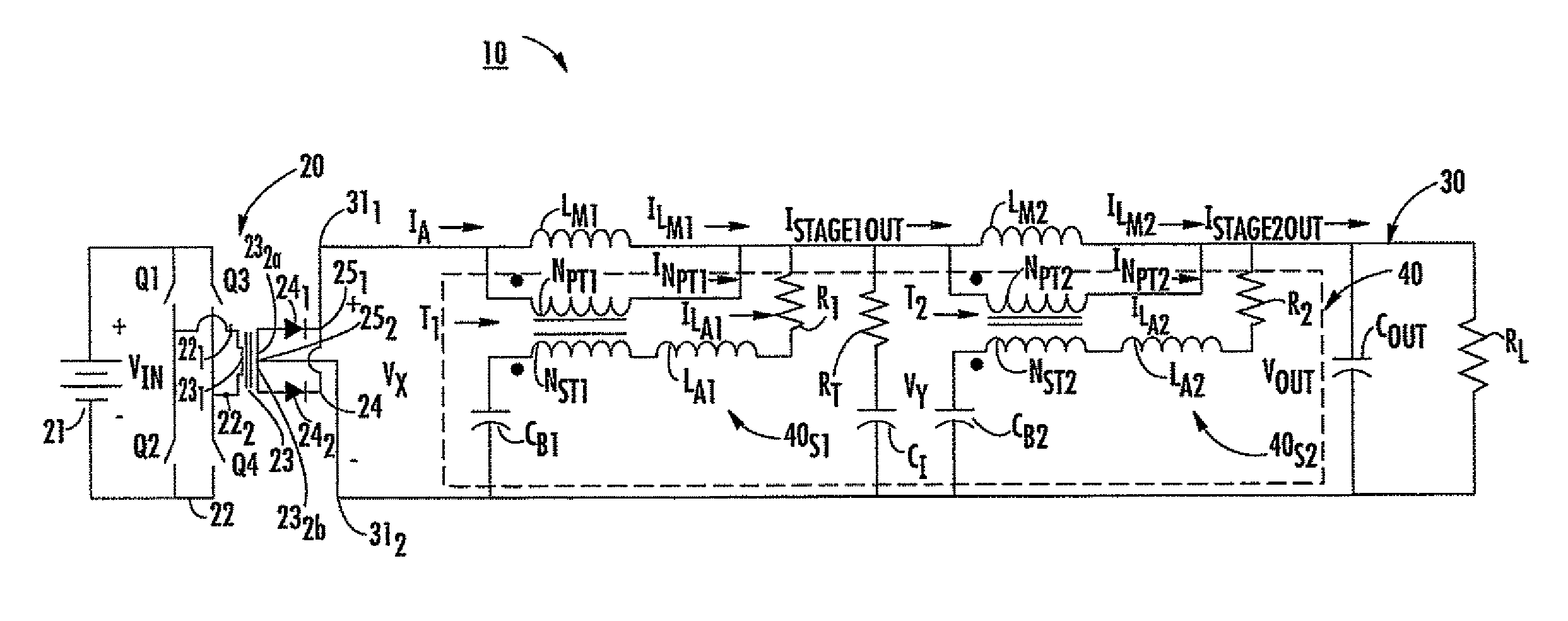
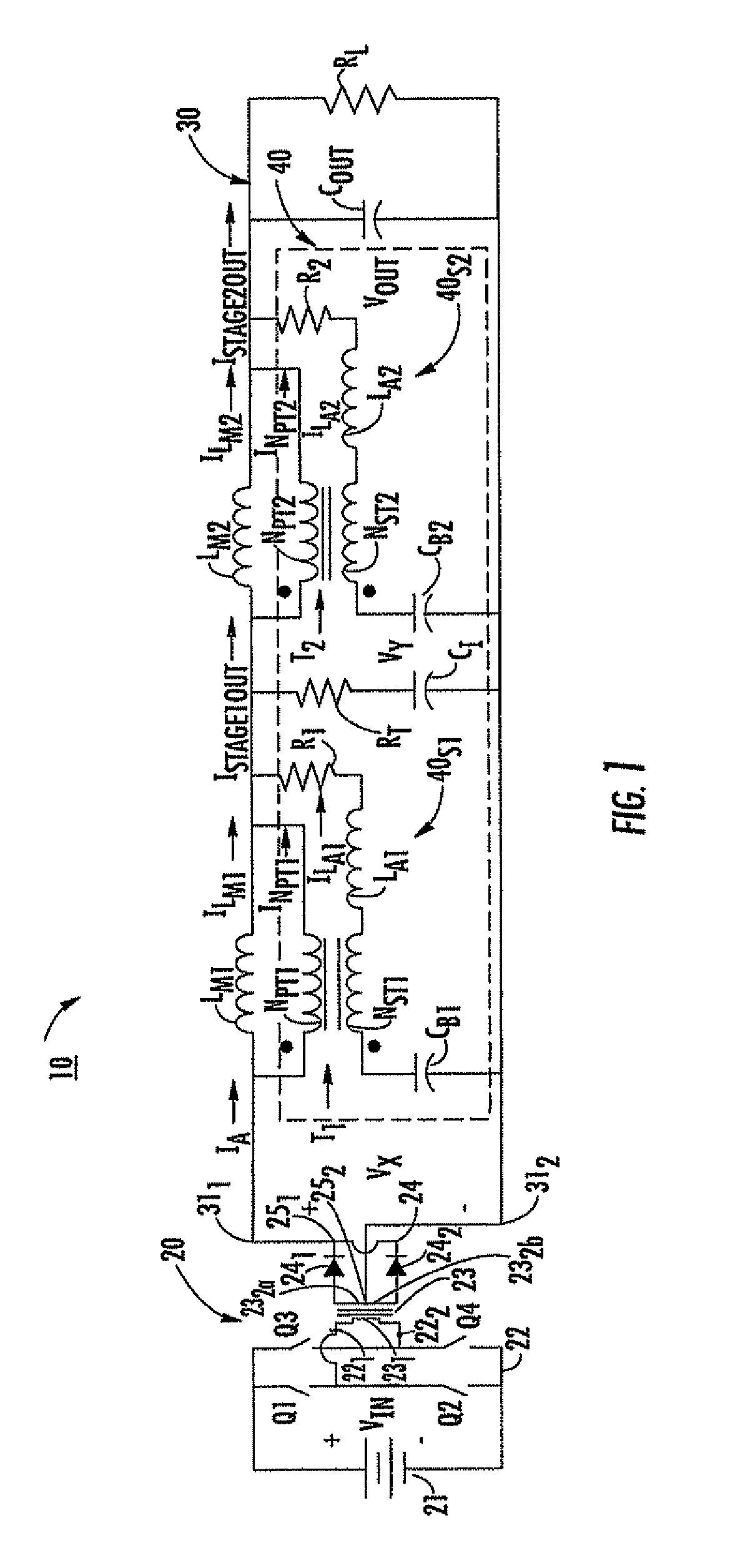
[0022]FIG. 1 is a simplified schematic diagram showing an exemplary embodiment of a power converter. The power converter, denoted generally by reference numeral 10, comprises a voltage source 20 and an output filter circuit 30 including an attenuation filtering circuit 40. The switching action of the power converter connected to the voltage source 20 produces a pulsating voltage Vx(t), which is applied to the output filter circuit 30. The pulsating voltage Vx(t) includes a DC voltage component with an AC voltage (ripple voltage) component superimposed thereon. The output filter circuit 30 includes a high attenuation filtering circuit 40 for removing the ripple voltage.

[0023]As shown in FIG. 1, the voltage source 20 comprises a voltage supply 21, a phase-shifted full-wave switched bridge circuit 22, a transformer 23, and a rectifying arrangement 24. The phase-shifted full-wave switched bridge circuit 22 includes first and second tap points 221, 222 across which an alternating voltage...


PUM


Abstract

A power converter includes an output filter circuit including first and second inductive elements; a voltage source coupled to the output filter circuit, the voltage source for generating a voltage across the output filter circuit, the voltage including an alternating voltage component, the alternating voltage component causing the application of an alternating current to the first inductive element of the output filter circuit; and an attenuation filtering circuit. The attenuation filtering circuit includes a first magnetically coupled inductive arrangement for generating a first opposing alternating current in response to the alternating voltage applied to the first inductive element of the output filter circuit; a first combining element for combining the first opposing alternating current with the alternating current to partially cancel the alternating current, thereby producing an attenuated alternating current applied to the second inductive element of the output filter circuit; a second magnetically coupled inductive arrangement for generating a second opposing alternating current in response to the attenuated alternating current applied to the second inductive element of the output filter circuit; and a second combining element for combining the second opposing alternating current with the attenuated alternating current to substantially cancel the attenuated alternating current.

Description

RELATED APPLICATIONS[0001]This application claims the benefit of U.S. Provisional Patent Application No. 60 / 873,823, filed on Dec. 8, 2006, the entire disclosure of which is incorporated herein by reference.FIELD OF THE INVENTION[0002]This invention relates to power supplies, and more particularly to low-noise or low-ripple power converters.BACKGROUND OF THE INVENTION[0003]Much of the advance in standard of living over the past twenty or so years results from the use of advanced communications, data processing, and environmental sensing techniques. The devices used in such communications, processing, and sensing generally become more useful as their sizes are decreased, such that more of them can be used. For example, computers and cellular phones require ever-smaller elements, and become more capable as the number of devices, which can be accommodated, increases. Similarly, lightweight and reliable sensors can be used in large numbers in vehicles to aid in control and, in the case ...

Claims


Application Information

Patent Timeline
IPC IPC(8): H02M1/12H02M1/14
CPCH02M1/126H02M3/28
Inventor SCHUTTEN, MICHAEL JOSEPHNASADOSKI, JEFFREY JOSEPHGLASER, JOHN STANLEYDE ROOIJ, MICHAEL ANDREW
Owner LOCKHEED MARTIN CORP
Why Eureka
Try Eureka