Context based configuration management system

a configuration management system and context-based technology, applied in the field of context-based configuration management system, to achieve the effect of improving enterprise-level assessments and forecasting, easy interoperability, and extensive individual and organizational inputs/comments

Active Publication Date: 2010-03-02
NASA
View PDF6 Cites 17 Cited by
  • Summary
  • Abstract
  • Description
  • Claims
  • Application Information

AI Technical Summary

Benefits of technology

[0006]The Context Based Configuration Management (CBCM) system is designed to track changes in, and status of, enterprise level programmatic operations. Enterprise decision making and operations rely on management of non-traditional configuration management (CM) components: estimates, agreements, goals, policies, strategies, plans, values, priorities, options, beliefs, etc. Additionally, enterprise operations have unique environments / contexts: reviews, workshops, firedrills, OMB and Congressional actions, procurements, demos, experiments, etc. The CBCM system will unify off-the-shelf decision history and decision map systems to commercial configuration management systems. Significant knowledge management (KM) enhancements can be made to both the mapping frameworks, as front ends to the CM system, as well adding intelligence to the CM components to improve enterprise level assessments and forecasting. Specific CM objects will be customized to handle both the unique configurable enterprise components as well as the unique enterprise contexts. The KM enhancements focus on collaborative decision / history map development including multi-level independent forward and backward linking between large numbers of independent CBCM systems via the Web. This Web-based inter-activity will allow significant and unobtrusive communications and context enhancements to provide more extensive individual and organizational inputs / comments to a given enterprise strategic decision making activity. Finally, adaptive middleware technologies need to be integrated with the system so that decision / configuration changes can easily inter-operate with a range of enterprise level management systems (portfolio, budget, reporting, scheduling, etc.).

Problems solved by technology

One problem faced in managing all or part of a large, complex project is determining, at an arbitrary time, the present status of each relevant activity associated with the project and the history of each of these activities.

Method used


Image

  • Context based configuration management system
  • Context based configuration management system
  • Context based configuration management system

Examples


Embodiment Construction

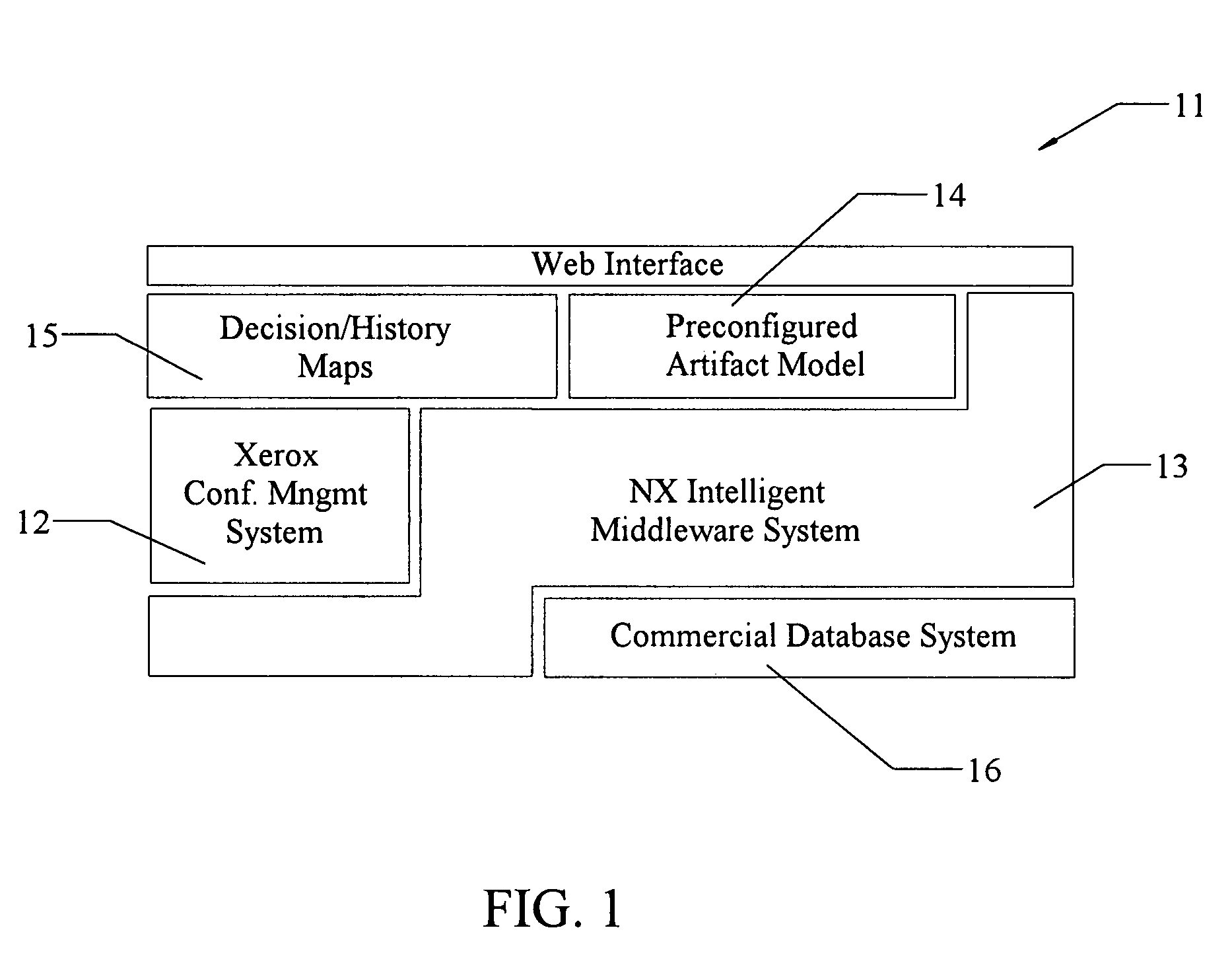
[0020]FIG. 1 schematically illustrates architecture of a context based configuration management (CBCM) system 11, including: a configuration management (CM) sub-system 12 for standard CM workflow capabilities; an intelligent middleware (IM) sub-system 13 for standard documentation management; a library 14 of preconfigured artifact models and flexible interfaces; a decision history and map sub-system 15, used to capture and archive the full context for a decision environment; and a database sub-system 16 providing multi-dimensional databases. The CM and IM sub-systems preferably rely upon an NX system, developed earlier by some of the inventors and issued as U.S. Pat. No. 6,968,338. The configuration management system 12 includes relevant information on the history to date of changes in one or more of the maps, the change-initiator, etc., for each preceding version of a map.

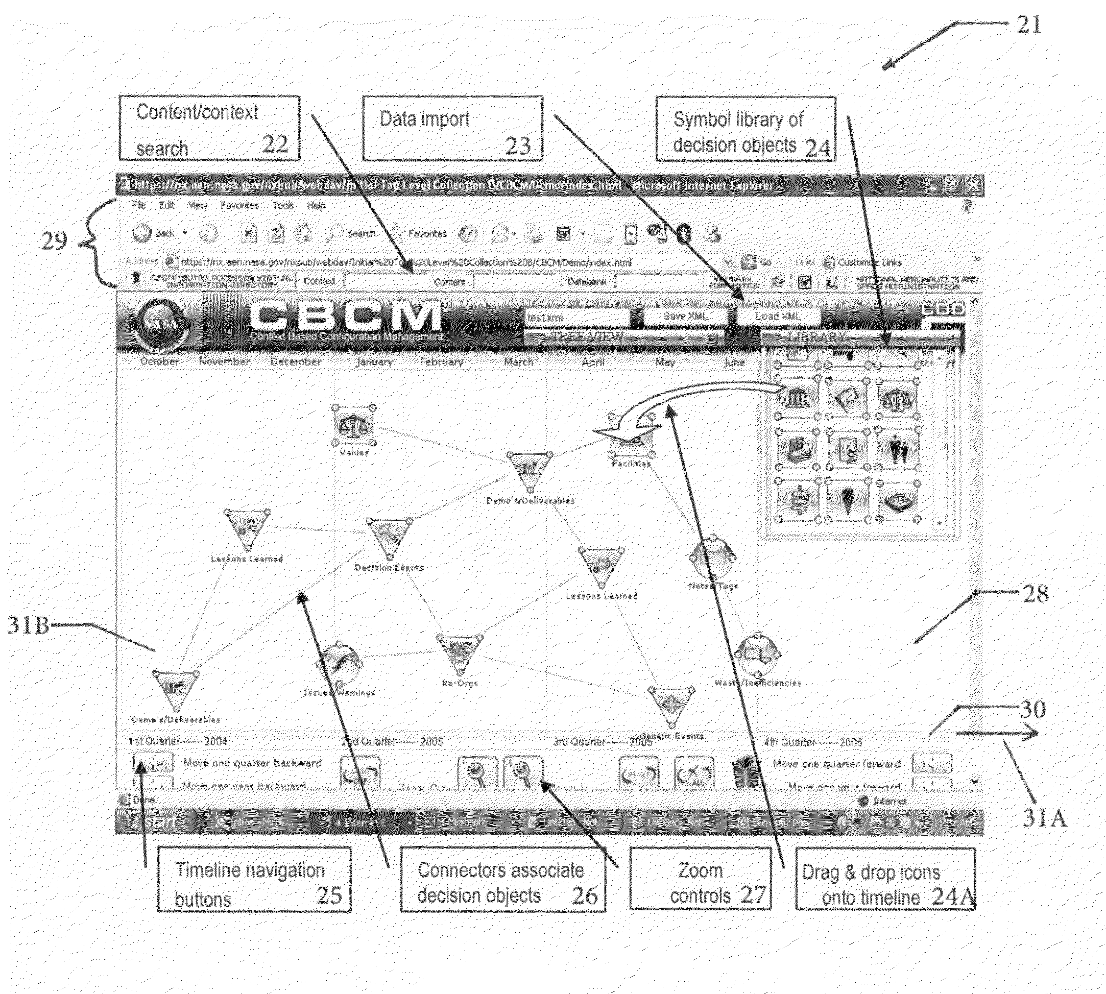
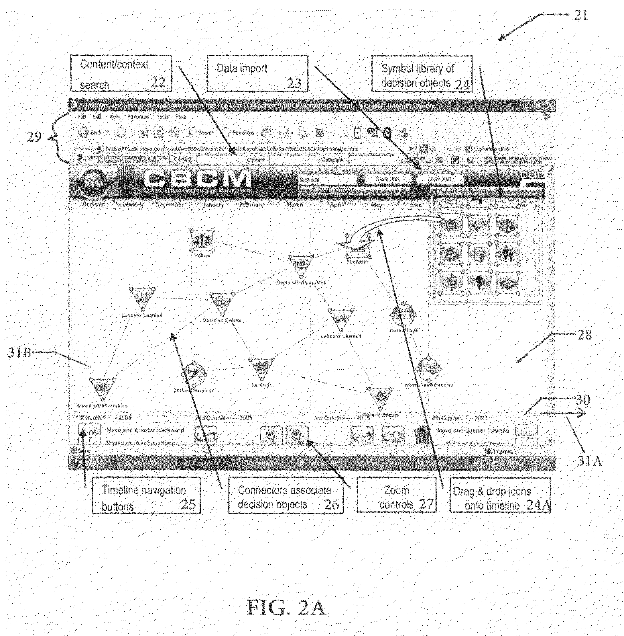
[0021]FIG. 2A illustrates one embodiment of a graphical user interface (GUI) 11, showing some of the key featur...


PUM


Abstract

A computer-based system for configuring and displaying information on changes in, and present status of, a collection of events associated with a project. Classes of icons for decision events, configurations and feedback mechanisms, and time lines (sequential and/or simultaneous) for related events are displayed. Metadata for each icon in each class is displayed by choosing and activating the corresponding icon. Access control (viewing, reading, writing, editing, deleting, etc.) is optionally imposed for metadata and other displayed information.

Description

ORIGIN OF THE INVENTION[0001]This invention was made, in part, by one or more employees of the U.S. government. The U.S. government has the right to make, use and / or sell the invention described herein without payment of compensation, including but not limited to payment of royalties.FIELD OF THE INVENTION[0002]This invention relates to monitoring and visually presenting information, in a decision tree, on a work flow process and status of and change in a document or operation.BACKGROUND OF THE INVENTION[0003]One problem faced in managing all or part of a large, complex project is determining, at an arbitrary time, the present status of each relevant activity associated with the project and the history of each of these activities. Project activities can be divided into classes, such as decisions, configurations and feedback / communication aspects. For complex projects, it would be helpful if each activity in a class could have an intuitive or self-evident icon or symbol that is clear...

Claims


Application Information

Patent Timeline
Patent Type & Authority Patents(United States)
IPC IPC(8): G06F7/00G06F17/00G06F17/30
CPCG06Q10/00
Inventor GAWDIAK, YURI O.GURRAM, MOHANA M.MALUF, DAVID A.MEDEROS, LUIS A.
Owner NASA
Why Eureka
Try Eureka