Combustor of gas turbine and combustion control method for gas turbine
a combustion control and gas turbine technology, applied in the direction of gas turbine plants, machines/engines, hot gas positive displacement engine plants, etc., can solve the problems of excessive lean state, decrease in combustion efficiency, fuel gas mixture, etc., to achieve the effect of improving flame holding performance, reducing the occurrence of unburned fuel between the first group and the second group, and improving flame holding performan
- Summary
- Abstract
- Description
- Claims
- Application Information
AI Technical Summary
Benefits of technology
Problems solved by technology
Method used
Image
Examples
embodiment 1
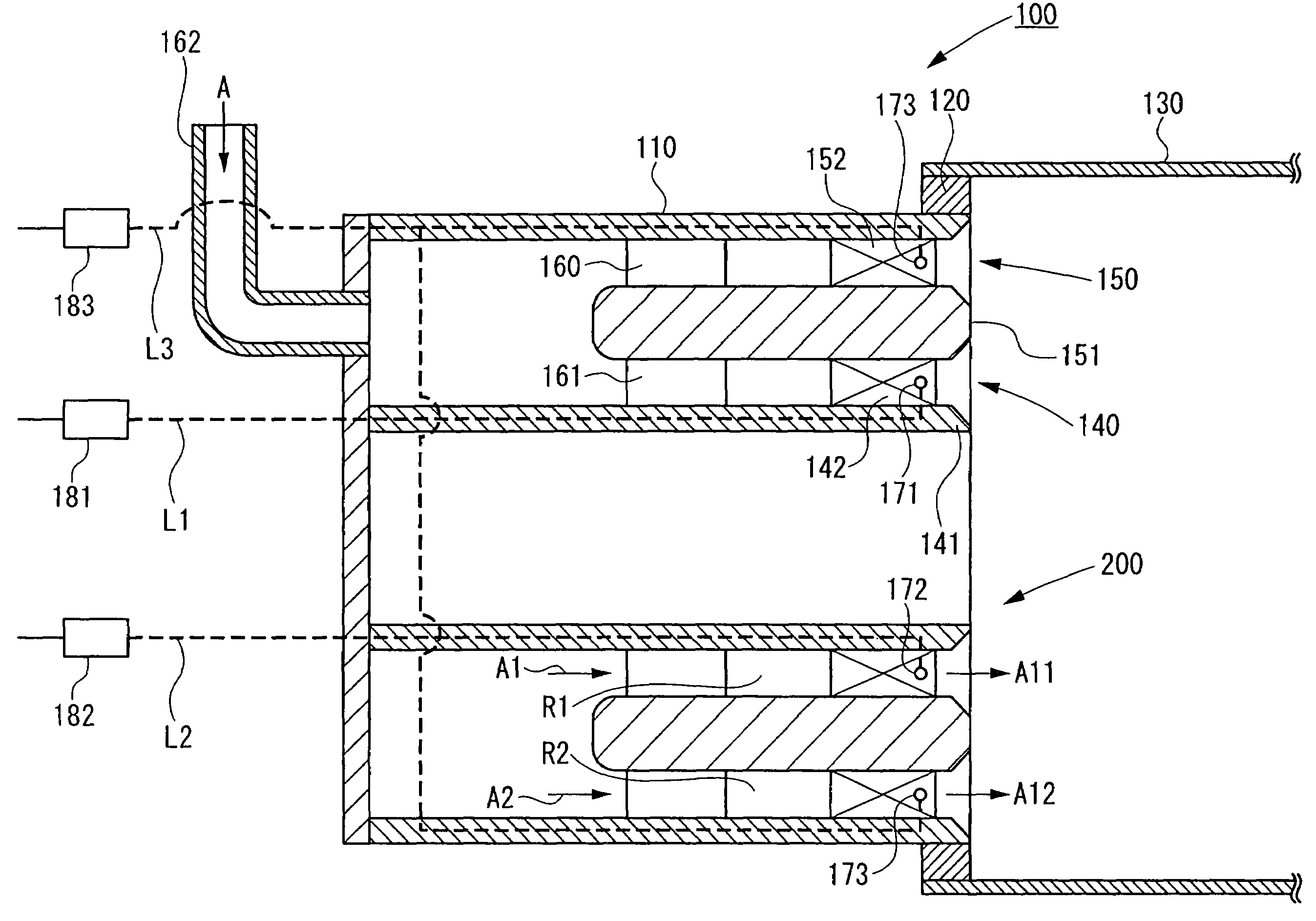
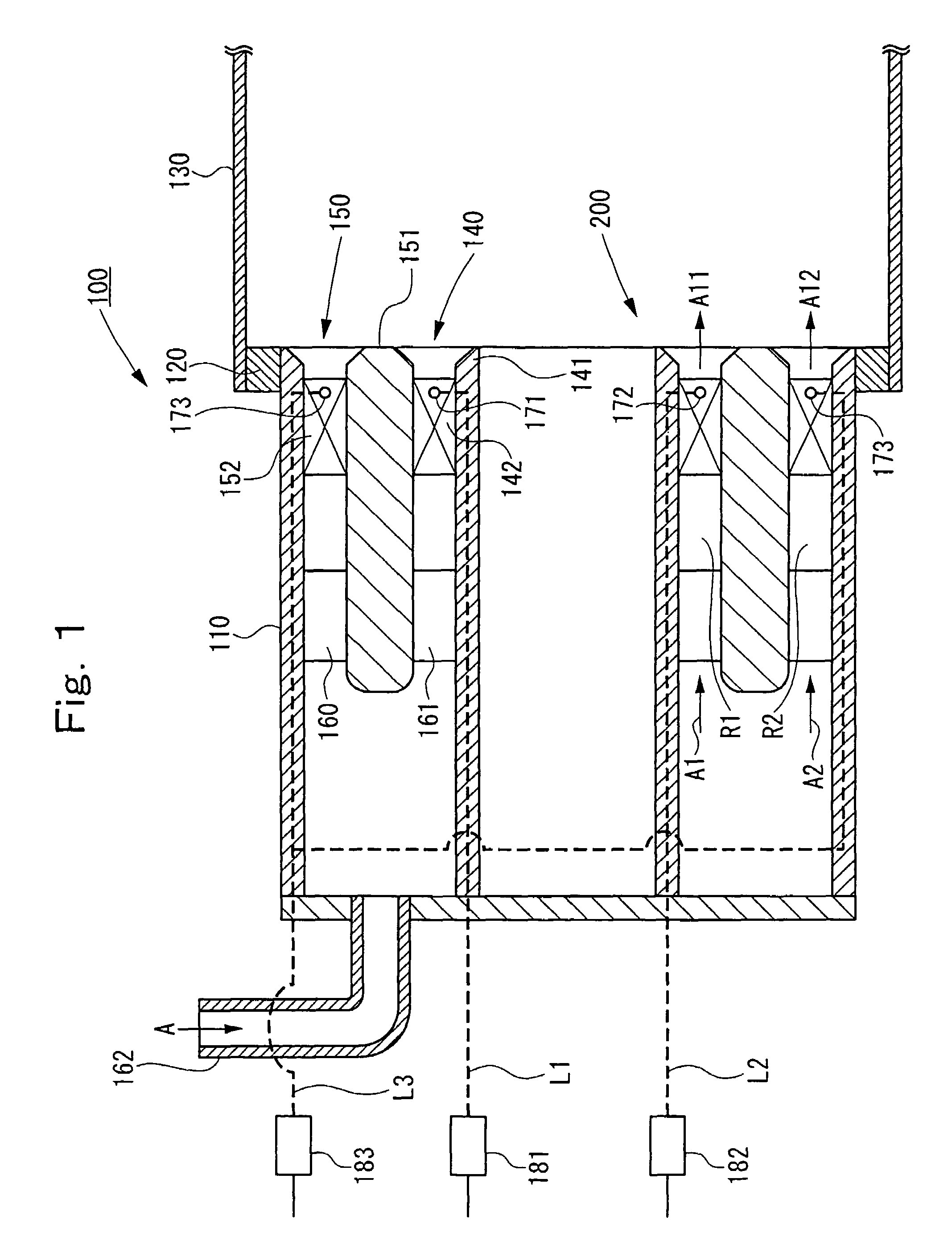
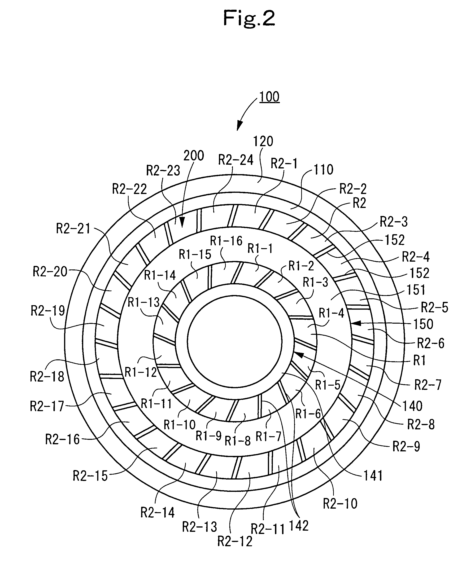
[0057]A combustor 100 of a gas turbine according to Embodiment 1 of the present invention is described with reference to FIG. 1 as a longitudinal sectional view, and FIG. 2 as a front view. The combustor 100 according to this Embodiment 1 is applied to a gas turbine at a high pressure ratio (a pressure ratio of 25 or higher) in the 1700° C. class being newly developed.
[0058]As shown in FIGS. 1 and 2, the rear edge of an inner tube 110 is connected to the leading edge of a transition pipe 130 via a connecting ring 120.
[0059]Inside the inner tube 110, an internal swirler 140 and an external swirler 150 are placed. That is, the internal swirler 140 on the inner peripheral side and the external swirler 150 on the outer peripheral side are disposed concentrically about the central axis of the inner tube 110. The internal swirler 140 and the external swirler 150 constitute a double swirler 200.
[0060]A swirler ring 141 of the internal swirler 140 is of a cylindrical shape, and is disposed ...
embodiment 2
[0107]Next, a combustor 100A of a gas turbine according to Embodiment 2 of the present invention will be described with reference to FIG. 6 as a front view.
[0108]In the combustor 100A of Embodiment 2, blocking members H for decreasing the flow areas of the divisional fluid passage R1-8 and the divisional fluid passage R1-16 are provided at the rear edge of the divisional fluid passages R1-8 and R1-16.
[0109]In other words, at the rear edge of the inner tube 110, the blocking members H for inhibiting the outflow of a fluid are disposed at the boundary portions between the divisional fluid passages R1-1 to R1-8 of the first group and the divisional fluid passages R1-9 to R1-16 of the second group.
[0110]Thus, the swirl air flow A11 exiting from the divisional fluid passages R1-1 to R1-7 of the first group, and the swirl air flow A12 exiting from the divisional fluid passages R1-9 to R1-15 of the second group are not mixed in the neighborhood of the rear end of the inner tube 110 (the do...
embodiment 3
[0116]Next, a combustor 100B of a gas turbine according to Embodiment 3 of the present invention will be described with reference to FIG. 7 as a longitudinal sectional view. This Embodiment 3 has the same basic configuration and uses the same combustion control method as those in Embodiment 1.
[0117]In the Embodiment 3, of the fuel injection holes 171 of the first group, the fuel injection holes 171 facing the divisional fluid passage R1-1 and the divisional fluid passage R1-8 have larger hole diameters. That is, the fuel injection holes 171 facing the divisional fluid passages R1-1 and R1-8 adjacent to the divisional fluid passages R1-9 to R1-16 of the second group among the divisional fluid passages R1-1 to R1-8 of the first group have larger hole diameters.
[0118]In the first group, therefore, the concentration of the fuel gas exiting from the divisional fluid passages R1-1 and R1-8 is higher than the concentration of the fuel gas exiting from the divisional fluid passages R1-2 to ...
PUM
 Abstract
Description
Claims
Application Information
 - R&D
- Intellectual Property
- Life Sciences
- Materials
- Tech Scout
- Unparalleled Data Quality
- Higher Quality Content
- 60% Fewer Hallucinations
Browse by: Latest US Patents, China's latest patents, Technical Efficacy Thesaurus, Application Domain, Technology Topic, Popular Technical Reports.
© 2025 PatSnap. All rights reserved.Legal|Privacy policy|Modern Slavery Act Transparency Statement|Sitemap|About US| Contact US: help@patsnap.com


