Well casing-based geophysical sensor apparatus, system and method

a sensor and well casing technology, applied in the field of oil well monitoring operations, can solve the problems of time-consuming and expensive operations, source and receiver on the surface, and conventional borehole geophysics is less expensive, but has an upfront cost and a downtime cos

Inactive Publication Date: 2010-03-09
LAWRENCE LIVERMORE NAT SECURITY LLC
View PDF17 Cites 33 Cited by
  • Summary
  • Abstract
  • Description
  • Claims
  • Application Information

AI Technical Summary

Benefits of technology

[0006]One aspect of the present invention includes a geophysical sensor apparatus, comprising: an elongated well casing capable of being emplaced in a borehole; a sensor located outside the well casing for detecting a geophysical parameter at an emplacement depth; means for communicating detection data from the sensor out to a remote monitoring location; and a centralizer affixed to a section of the well casing so that during emplacement the well casing and the sensor are spaced from the borehole sidewalls to protect the well casing and the sensor from damage.
[0007]Another aspect of the present invention includes a well casing-based geophysical sensor apparatus, comprising: a plurality of elongated well casings capable of being serially connected into a casing string during emplacement in a borehole; a plurality of sensors located outside the well casings along various sections thereof corresponding to various emplacement depths, said sensors being of at least one type per emplacement depth for detecting at least one type of geophysical parameter per emplacement depth; means for communicating detection data from the sensors out to a remote monitoring location; and a plurality of centralizers fixedly connected to different sections of the well casings so that during emplacement the well casings and the sensors are spaced from the borehole sidewalls to protect the well casings and the sensors from damage.
[0008]Another aspect of the present invention includes a well casing-based geophysical sensor system comprising: at least two geophysical sensor apparatuses each capable of emplacement in one of a distributed network of boreholes, with each geophysical sensor apparatus comprising: a plurality of elongated well casings capable of being serially connected into a casing string during emplacement in a borehole; a plurality of sensors located outside the well casings along various sections thereof corresponding to various emplacement depths, said sensors being of at least one type per emplacement depth for detecting at least one type of geophysical parameter per emplacement depth; means for communicating detection data from the sensors out to a remote monitoring location; and a plurality of centralizers fixedly connected to different sections of the well casings so that during emplacement the well casings and the sensors are spaced from the borehole sidewalls to protect the well casings and the sensors from damage.

Problems solved by technology

However, moving sondes in boreholes for logging or crosshole tomography, or moving sources and receivers on the surface for reflection seismology, are time consuming and expensive operations.
Conventional borehole geophysics is less expensive but has an upfront cost and a downtime cost.
Additionally, conventional borehole techniques tend to have a narrow filed of view.
Alternatively, prior art practices have utilized sensors which were placed inside the casings, which prevented operation of oil recovery operation during that monitoring / sensing period.
In any of these monitoring methods, the time interval between surveys is generally limited to the survey costs and the reluctance to remove wells from production due to downtime costs.

Method used


Image

  • Well casing-based geophysical sensor apparatus, system and method
  • Well casing-based geophysical sensor apparatus, system and method
  • Well casing-based geophysical sensor apparatus, system and method

Examples


Embodiment Construction

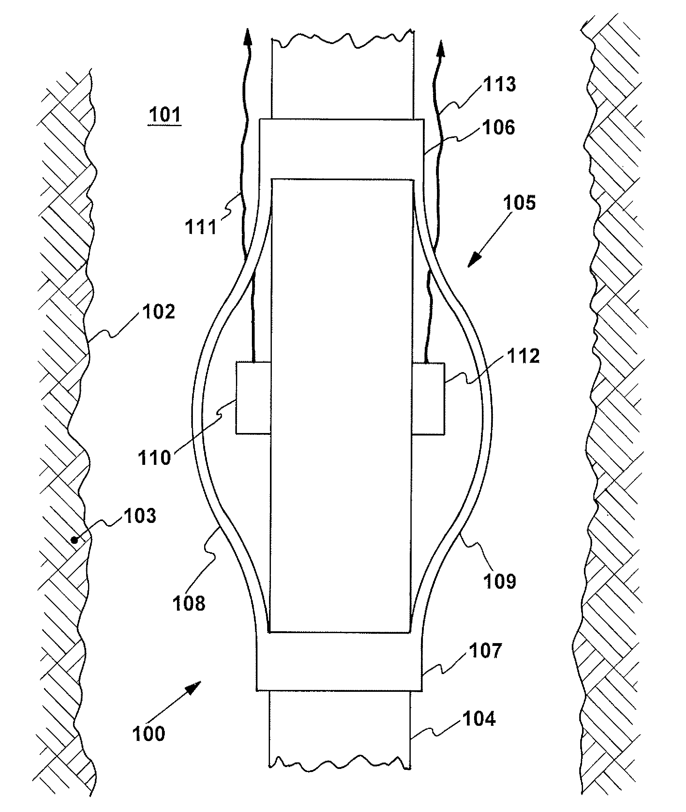
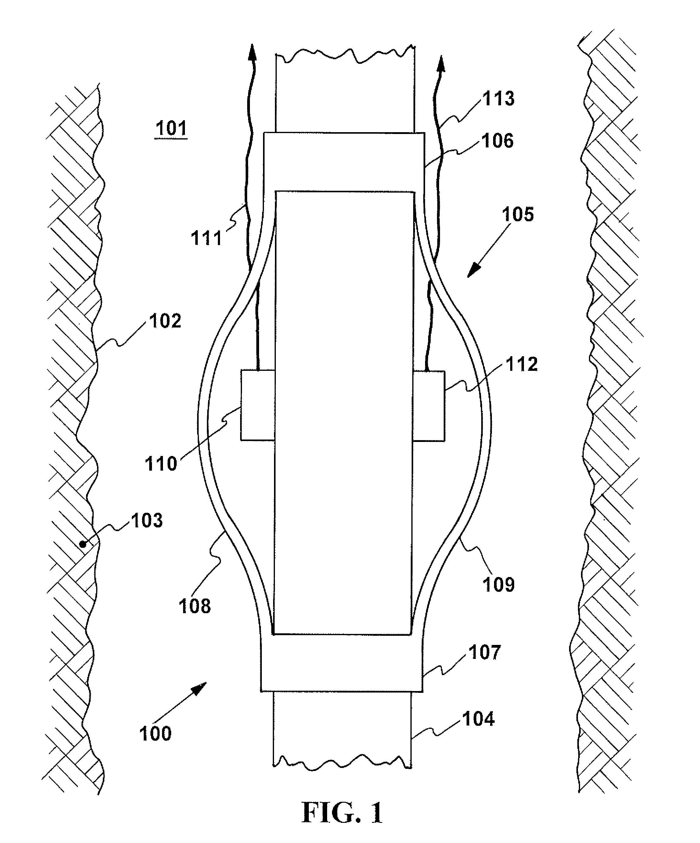
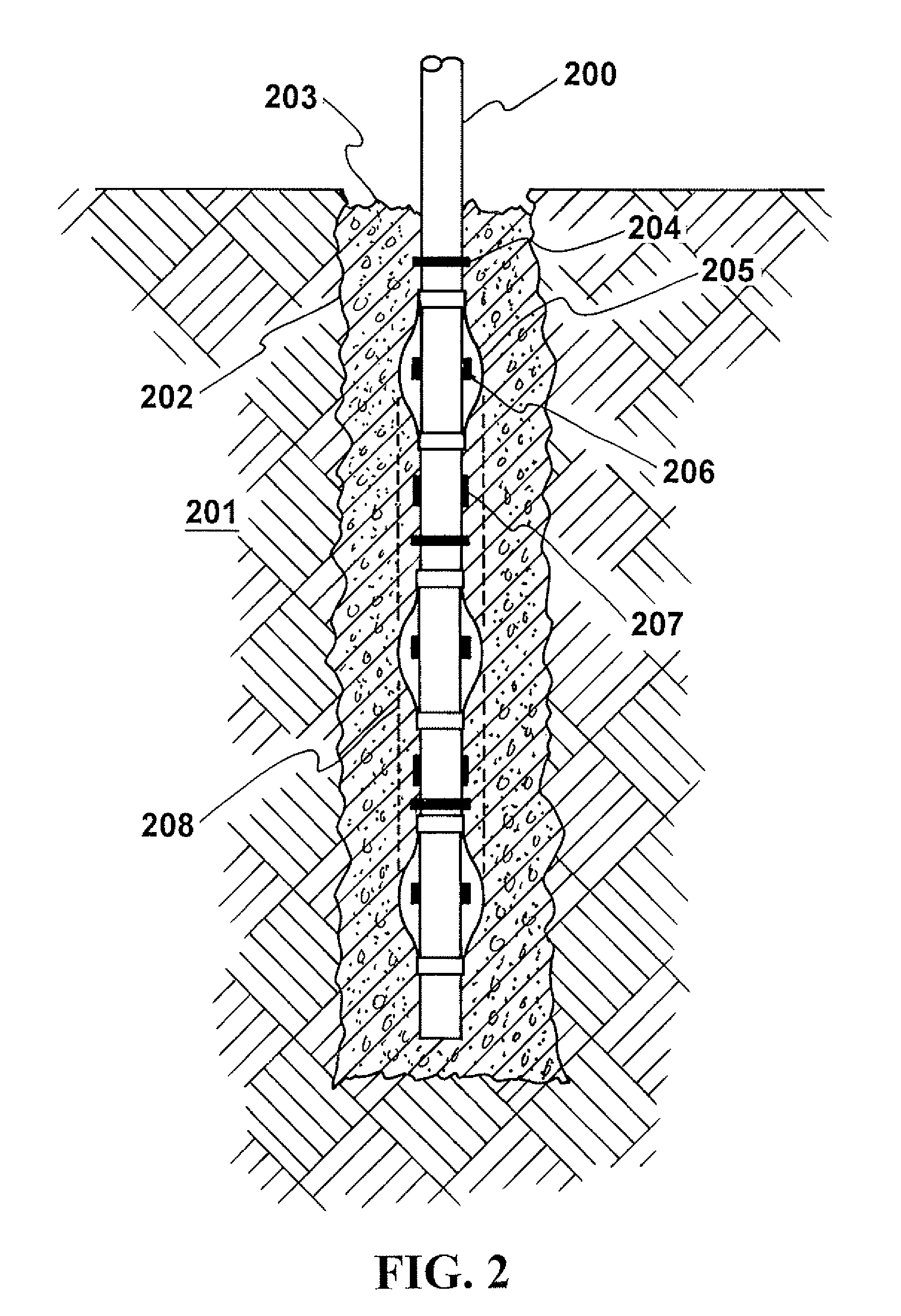
[0017]Generally, the present invention is directed to a geophysical sensor apparatus, system, and method using well casings to emplace geophysical sensors at various in-ground emplacement depths in a well borehole, and to subsequently monitor and characterize down-well conditions of, for example, an oil reservoir. As such, the present invention may be described as a “smart casing” for its ability to collect geophysical data, and not function simply as a mechanical structure. Additionally, the present invention includes centralizers fixedly secured to the well casings to protect geophysical sensors and wires / cables from damage which would otherwise be possible when emplacing the sensor-fitted casing down a borehole due to the external location of the sensors and wires to the well casing. Such exterior location is required because in order to operate properly, geophysical sensors must come in contact with the surrounding formation rock, typically achieved by grouting, i.e. cementing, ...


PUM


Abstract

A geophysical sensor apparatus, system, and method for use in, for example, oil well operations, and in particular using a network of sensors emplaced along and outside oil well casings to monitor critical parameters in an oil reservoir and provide geophysical data remote from the wells. Centralizers are affixed to the well casings and the sensors are located in the protective spheres afforded by the centralizers to keep from being damaged during casing emplacement. In this manner, geophysical data may be detected of a sub-surface volume, e.g. an oil reservoir, and transmitted for analysis. Preferably, data from multiple sensor types, such as ERT and seismic data are combined to provide real time knowledge of the reservoir and processes such as primary and secondary oil recovery.

Description

[0001]The United States Government has rights in this invention pursuant to Contract No. W-7405-ENG-48 between the United States Department of Energy and the University of California for the operation of Lawrence Livermore National Laboratory.I. FIELD OF THE INVENTION[0002]The present invention relates to oil well monitoring operations and more particularly relates to a geophysical sensor apparatus, system, and method using well casings to emplace sensors protected by centralizers down into a well borehole to monitor and characterize conditions in, for example, an oil reservoir.II. BACKGROUND OF THE INVENTION[0003]Large capital investments are typically required to produce any oil reservoir, and much of that investment is in the construction of deep wells which are located in the very part of the reservoir that is of greatest interest to characterize and monitor, i.e. where the oil is. One of the primary goals, therefore is to improve recovery efficiency for existing resources becau...

Claims


Application Information

Patent Timeline
Patent Type & Authority Patents(United States)
IPC IPC(8): E21B17/10E21B47/01
CPCE21B47/01E21B47/017
Inventor DAILY, WILLIAM D.
Owner LAWRENCE LIVERMORE NAT SECURITY LLC
Why Eureka
Try Eureka