Structured dielectric for coaxial cable

a technology of coaxial cable and dielectric, which is applied in the direction of power cables, cables, insulated conductors, etc., can solve the problems of air-filled cable electrical performance deterioration, signal may experience attenuation, and cable bending

Active Publication Date: 2010-03-09
ALCATEL LUCENT SAS +1
View PDF11 Cites 13 Cited by
  • Summary
  • Abstract
  • Description
  • Claims
  • Application Information

AI Technical Summary

Problems solved by technology

During transmission, the signal may experience attenuation due to the resistance of the inner and outer conductors and the loss factor of the dielectric material.
For the inner and outer conductors, economic and mechanical constraints usually result in the selection of a particular type of metal.
However, such cables are quite vulnerable to bending, as air is unlikely to stop the inner and outer conductors' from contacting each other if the cable is abruptly bent.
In addition, the electrical performance of an air-filled cable will deteriorate rapidly if any moisture intrudes.
Cables which use a solid polymer dielectric are also less expensive, but are less efficient at transmitting and receiving signal because air has a much lower dielectric constant than solid polymers.
These cables may also be vulnerable to moisture migration between the insulation and the inner and outer conductors.
Moisture may react with the metallic surface of the conductors, causing corrosion to develop.
These techniques can only add a limited amount of air without impairing the dielectric's ability to provide mechanical stability.
If water collects in these spaces; it may significantly degrade the quality of the cable.
More specifically, water can significantly increase the dielectric constant, thereby producing power loss and corrosion of the metallic conductors.
Even worse, water can flow into the cable if a terminal end is not sealed.
In such cases, water can quickly fill the gap between the inner and outer conductors, causing the dielectric constant to rise rapidly.

Method used


Image

  • Structured dielectric for coaxial cable
  • Structured dielectric for coaxial cable
  • Structured dielectric for coaxial cable

Examples


Embodiment Construction

[0030]Referring now to the drawings, in which like numerals refer to like components or steps, there are disclosed broad aspects of various exemplary embodiments.

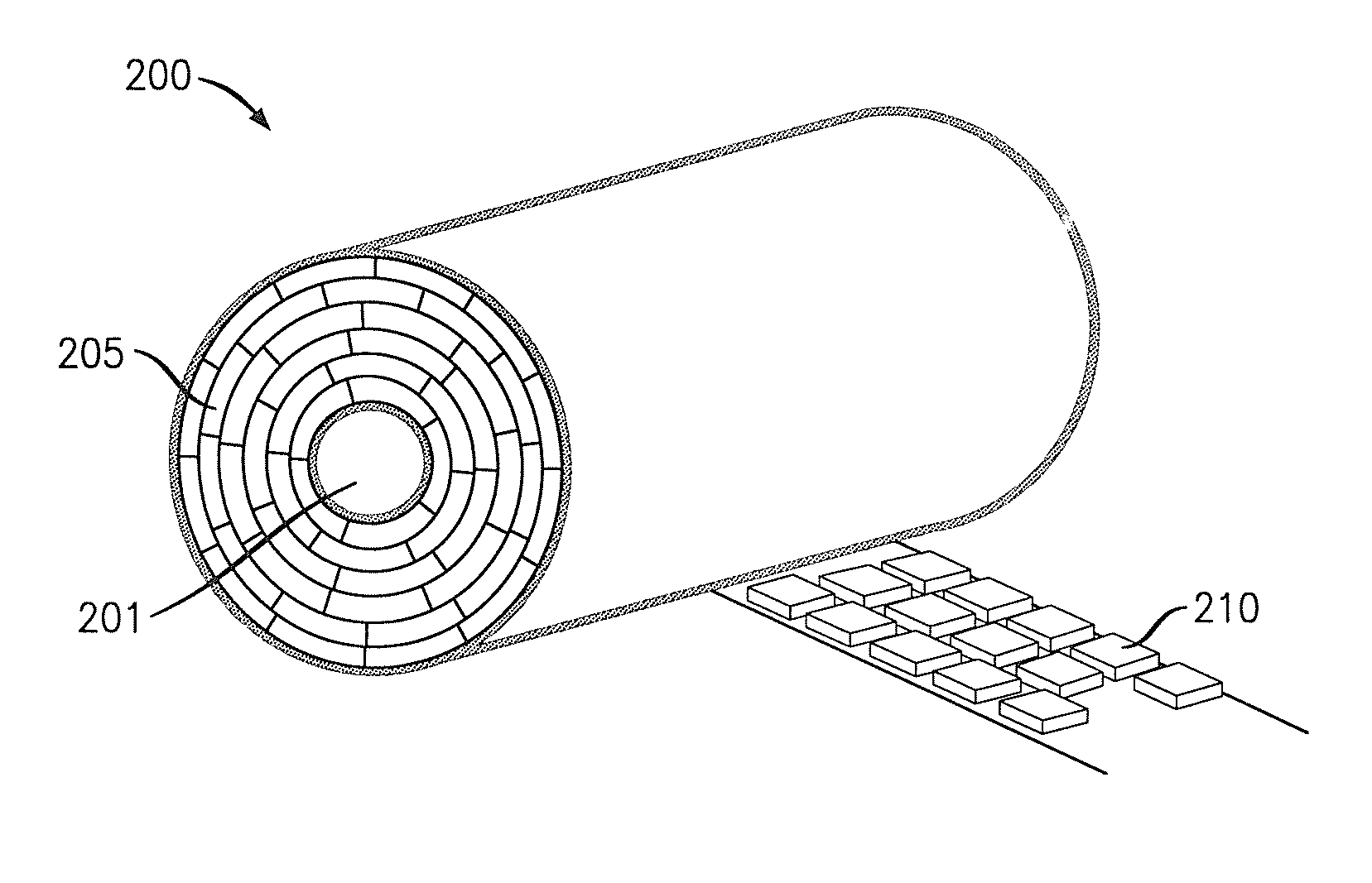
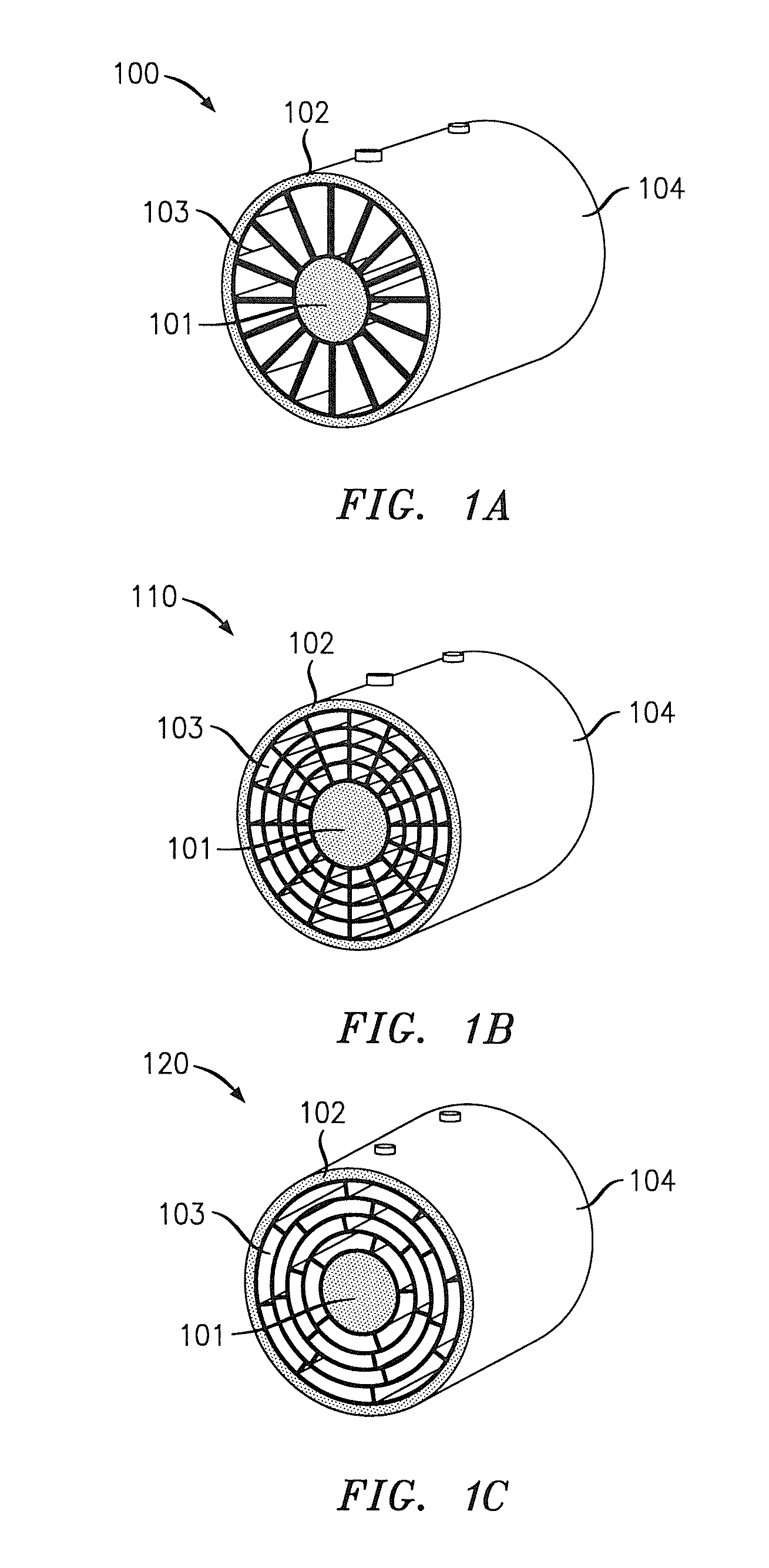
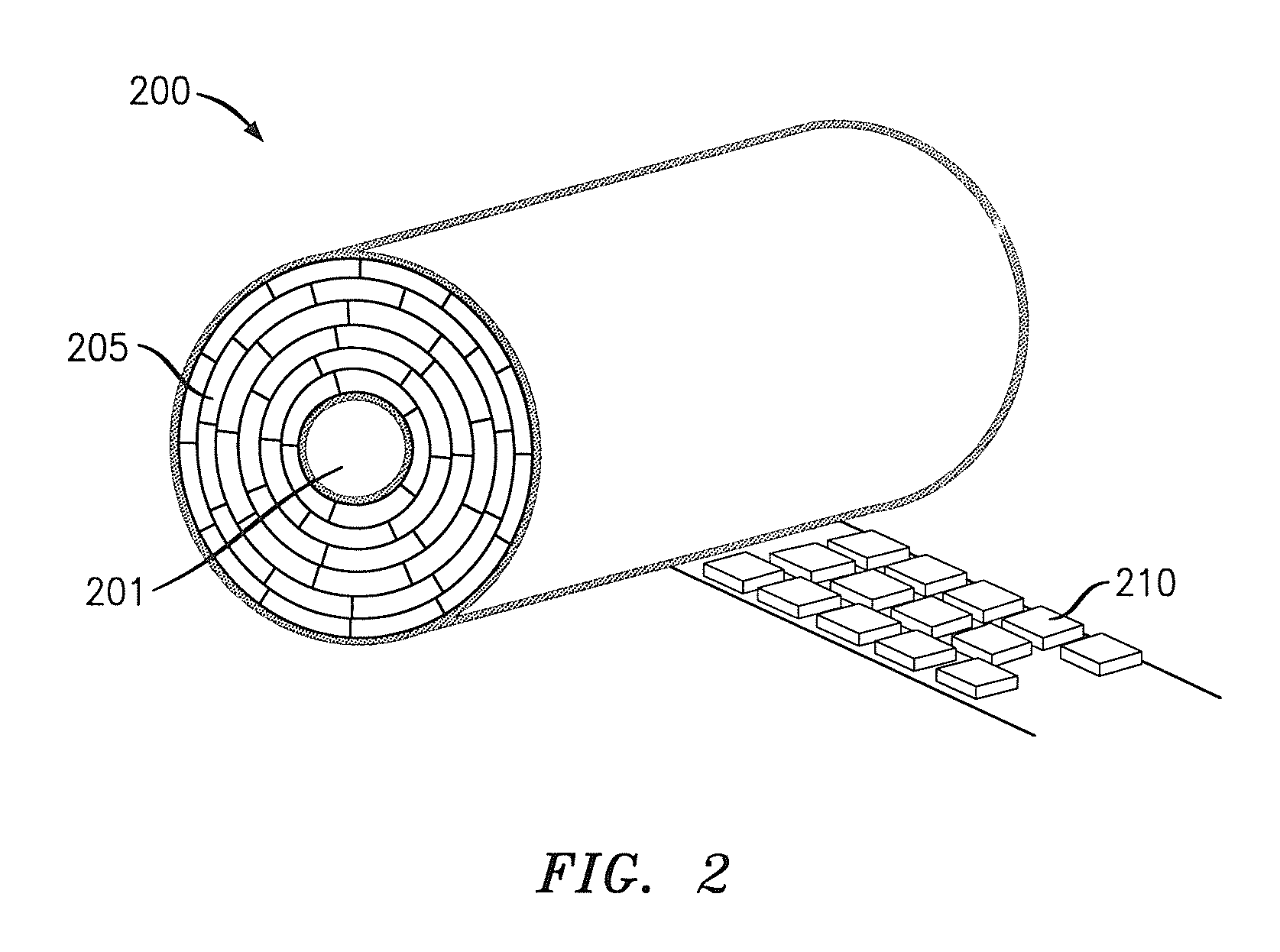
[0031]FIGS. 1A, 1B, and 1C show cross-sectional views of structured dielectric layers. The three coaxial cables 100, 110, and 120 depicted in FIGS. 1A, 1B, and 1C, respectively, share three common elements.

[0032]First, an inner conductor 101 is located in the center of each cable 100, 110, 120. Inner conductor 101 may be fabricated from an electrically conductive metal. It should be apparent that any electrically conductive metal may be used according to cost and design requirements. Thus, in various exemplary embodiments, the metal used for conductor 101 is copper, silver, copper-plated aluminum, or any other conductive metal.

[0033]Second, an outer conductor 102 defines the circumference of each cable 100, 110, and 120. Outer conductor 102 may consist of braided copper wire. However, it should be apparent that any electric...


PUM

PropertyMeasurementUnit
dielectric constantaaaaaaaaaa
relative permittivityaaaaaaaaaa

Abstract

A geometrically-structured coaxial cable may prevent infiltration of water vapor and other contaminants by using a closed cell structure. The cable may be fabricated by wrapping bubble tape around its central conductor. Alternatively, plastic may be extruded through channels to create a plurality of layers. In either case, these layers are staggered in a zig-zag pattern to ensure that no radial spokes connect the inner and outer conductors of the coaxial cable without passing through a plurality of dielectric layers.

Description

BACKGROUND OF THE INVENTION[0001]1. Field of the Invention[0002]This invention relates generally to radio / microwave frequency hardware. In particular, it relates to a dielectric that prevents moisture from entering coaxial cables and methods of manufacturing cables incorporating such a dielectric.[0003]2. Description of Related Art[0004]Coaxial cables are widely used for the transmission of analog and digital signals at radio and microwave frequencies. A typical coaxial cable consists of a metallic inner conductor, a dielectric material, and a metallic outer conductor arranged in a circular, concentric manner. The signal transmitted across the cable appears as an electromagnetic field in the dielectric, causing electrical currents to flow through the inner and outer conductors. During transmission, the signal may experience attenuation due to the resistance of the inner and outer conductors and the loss factor of the dielectric material.[0005]In order to minimize the transmission lo...

Claims


Application Information

Patent Timeline
Patent Type & Authority Patents(United States)
IPC IPC(8): H01B7/00
CPCH01B11/1839Y10T29/49123H01B11/1847
Inventor HESSELBARTH, JANMAHLANDT, ERHARDLYONS, ALAN MICHAEL
Owner ALCATEL LUCENT SAS
Why Eureka
Try Eureka