Parabolic antenna with rinsing connection

a technology of parabolic antennas and level radars, applied in the field of level measurement, can solve the problems of no signal being transmitted at all, deteriorating the quality of measuring, etc., and achieve the effect of not deteriorating or falsifying the measuring result, and improving the quality of measuremen

Active Publication Date: 2010-03-09
VEGA GRIESHABER GMBH & CO
View PDF11 Cites 42 Cited by
  • Summary
  • Abstract
  • Description
  • Claims
  • Application Information

AI Technical Summary

Benefits of technology

[0008]Thereby, simple and inexpensive individual manufacturing of the level radar or antenna may be possible, in that during final assembly, various antenna systems are equipped with corresponding individual outlet members. This may allow for high flexibility at low production cost.
[0038]Thereby, a method is provided, which may allow for the quality of the measuring signals to be maintained even under adverse environmental conditions, in that the exciter / receiver is rinsed with rinsing agent for cleaning.

Problems solved by technology

In particular, contamination of the antenna feed or the exciter, which may be caused e.g. by filling material dust or liquid, may significantly deteriorate the quality of measuring results.
In the extreme case, serious contamination of the exciter (which by the way may also be used as a radiation receiver) may even lead to no signals being transmitted at all.

Method used


Image

  • Parabolic antenna with rinsing connection
  • Parabolic antenna with rinsing connection
  • Parabolic antenna with rinsing connection

Examples


Embodiment Construction

[0049]In the following description of the figures, the same reference numerals will be used for like or similar elements.

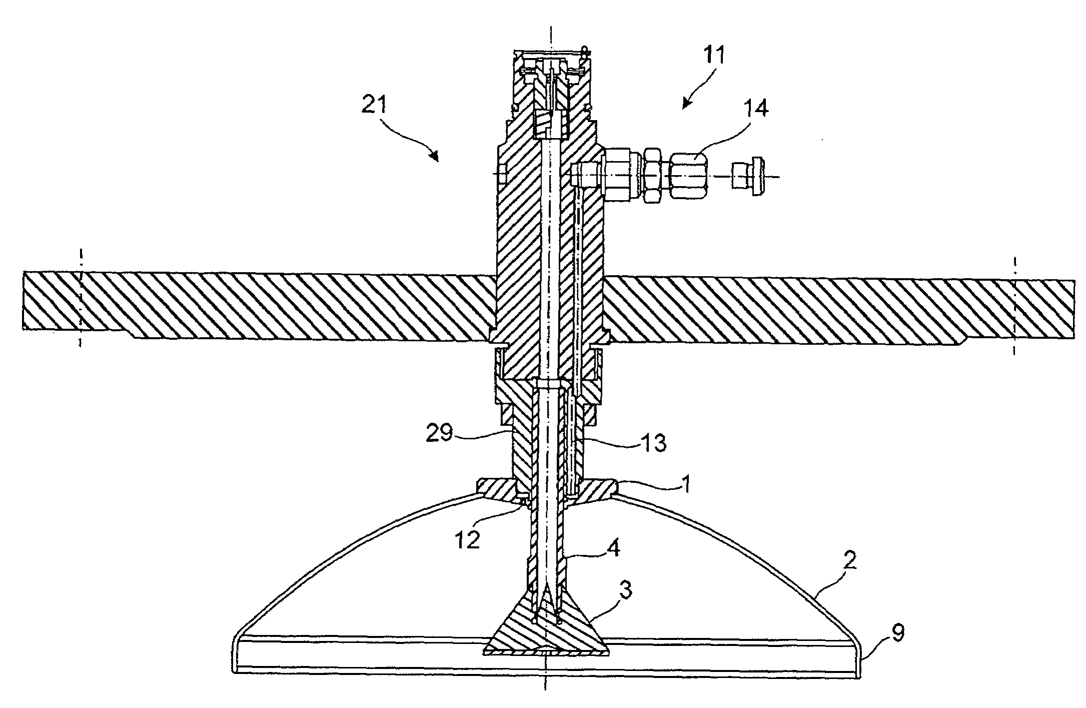
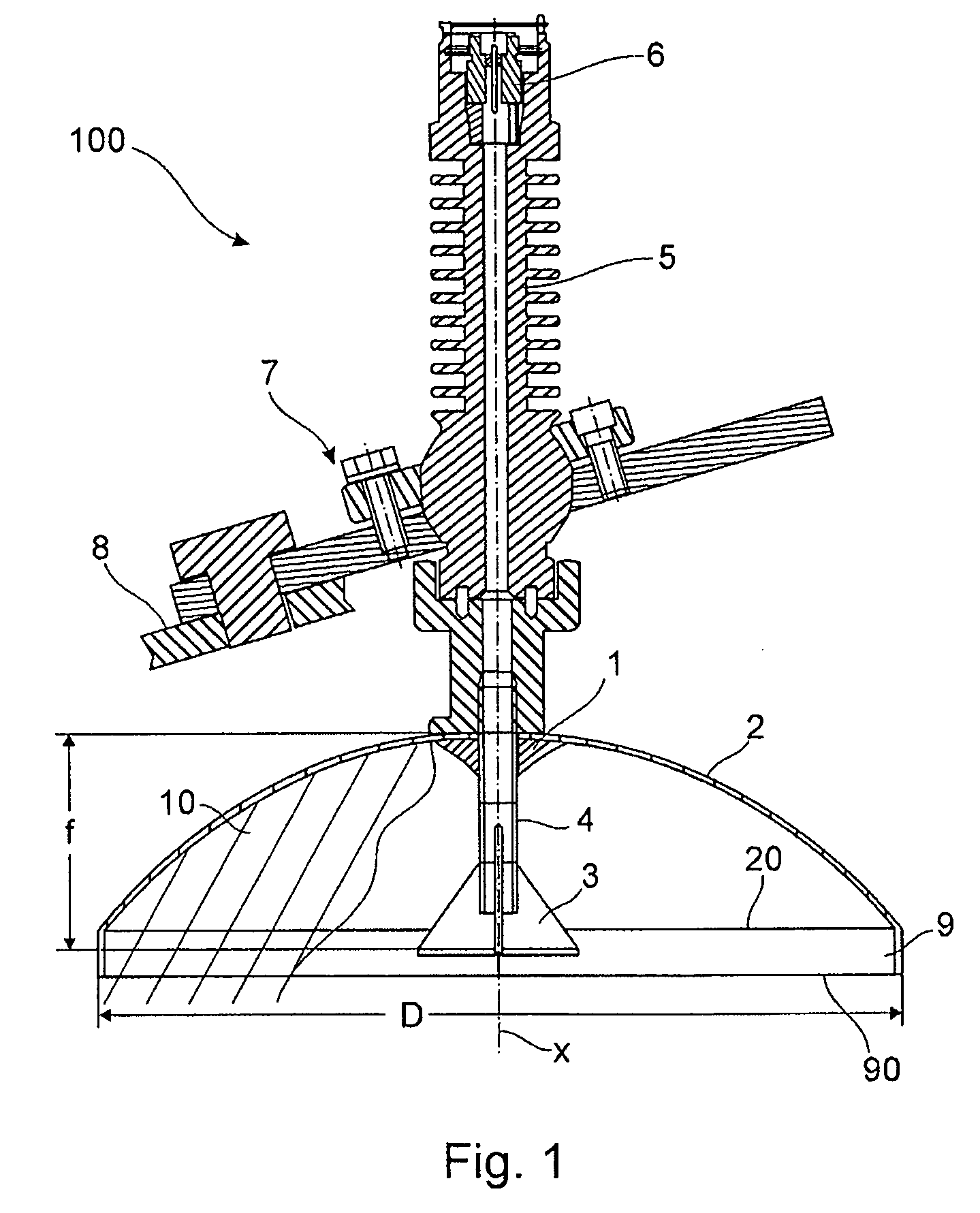
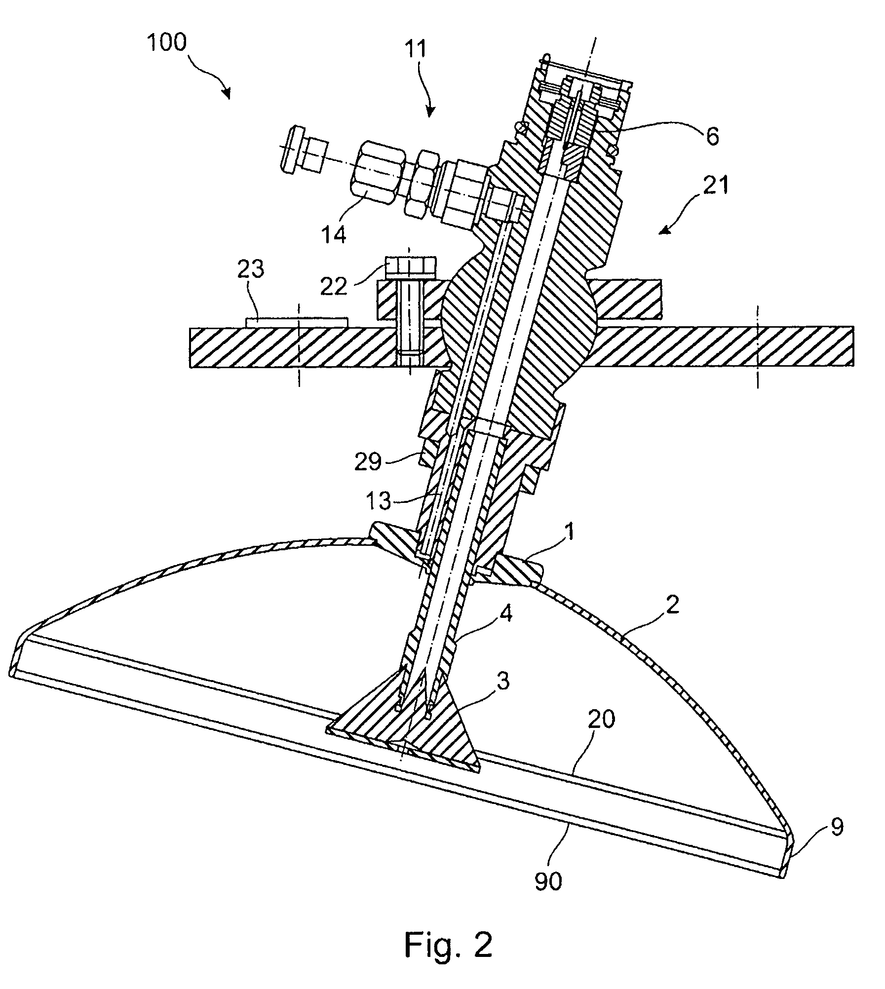
[0050]FIG. 1 shows a schematic cross-sectional view of a parabolic antenna according to an exemplary embodiment of the present invention. As may be seen in FIG. 1, the parabolic antenna 100 is substantially composed of a parabolic reflector 2 with a diffusing panel 1 and an exciter / receiver 3. Herein, the parabolic reflector 2 comprises a rotary parabolic reflector edge 20. The parabolic reflector edge 20 transitions into an additional collar 9 with an outside collar edge 90. Herein, the wall of the collar 9 extends approximately axially in parallel to a central parabolic reflector axis X of the parabolic reflector 2.

[0051]Furthermore, the parabolic antenna 100 comprises the exciter and / or receiver 3, which is arranged on the parabolic reflector axis X, and is spaced away from the backside wall of the parabolic reflector 2 with a wave-guiding member, e.g. an anten...


PUM


Abstract

Contamination at the exciter of a parabolic antenna can lead to impaired signal quality, or even system downtime. A parabolic antenna is described which in addition to a parabolic reflector and an exciter has a rinsing device, which is configured so as to rinse and clean the exciter with rinsing agent or protect it from contaminants. Herein, the rinsing agent is injected, dropped, or else blown from a rinsing outlet in an outlet member at the parabolic reflector onto the exciter. Mounting the rinsing outlet directly to the parabolic reflector allows for the exciter to be cleaned from the parabolic reflector.

Description

RELATED APPLICATIONS[0001]This application claims the benefit of the filing date of United States Provisional Patent Application No. 60 / 726,863 filed Oct. 14, 2005, and of German Patent Application No. 10 2005 049 243.6 filed Oct. 14, 2005, the disclosures of which are hereby incorporated herein by reference.TECHNICAL FIELD[0002]This invention relates to level measuring. In particular, the present invention relates to a parabolic antenna for a level radar, a level radar comprising such a parabolic antenna, the utilization of such a parabolic antenna for level measuring, and a method for measuring a level with a parabolic antenna.BACKGROUND TO THE INVENTION[0003]Known level measuring instruments have a parabolic antenna, which emits or receives radar or microwaves for determining the filling level of a medium in a filling material container. In this case, the parabolic antenna of such a level measuring instrument is arranged e.g. inside a container.[0004]The quality of the measuring ...

Claims


Application Information

Patent Timeline
Patent Type & Authority Patents(United States)
IPC IPC(8): H01Q19/12
CPCG01F23/284H01Q1/44H01Q19/13
Inventor KIENZLE, KLAUSLENK, FRITZ
Owner VEGA GRIESHABER GMBH & CO
Why Eureka
Try Eureka