
Head suspension with flexure vibration clearance

a head suspension and vibration clearance technology, applied in the direction of head support, record information storage, instruments, etc., can solve the problems of high flexibility design and structure cannot suppress the color change at the curved portion, and achieve the effect of high design flexibility and suppression of color change or discoloration on the load beam side or the base plate sid

Active Publication Date: 2010-03-09
NHK SPRING CO LTD
View PDF5 Cites 41 Cited by
  • Summary
  • Abstract
  • Description
  • Claims
  • Application Information

AI Technical Summary

Benefits of technology

The present invention provides a head suspension that allows for high flexibility in design while preventing color change or discoloration on the load beam caused by vibration contact. This is achieved by adding a recessed portion or through-hole portion on at least one of the load beam or base to avoid vibration contact of the flexure. This design allows for high flexibility without the need to elongate the cut portion, reducing the risk of color change or discoloration.

Problems solved by technology

However, this structure involves a restraint for layout in view of base material formation of the flexure, and thereby design with high flexibility can not be achieved.
Additionally, this structure can not suppress the color change at the curved portion, either.

Method used


Image

  • Head suspension with flexure vibration clearance
  • Head suspension with flexure vibration clearance
  • Head suspension with flexure vibration clearance

Examples


first embodiment

[0027]First, general constitution of a head suspension according to a first embodiment will be explained.

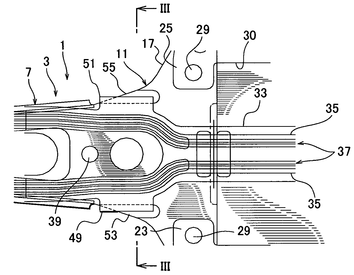
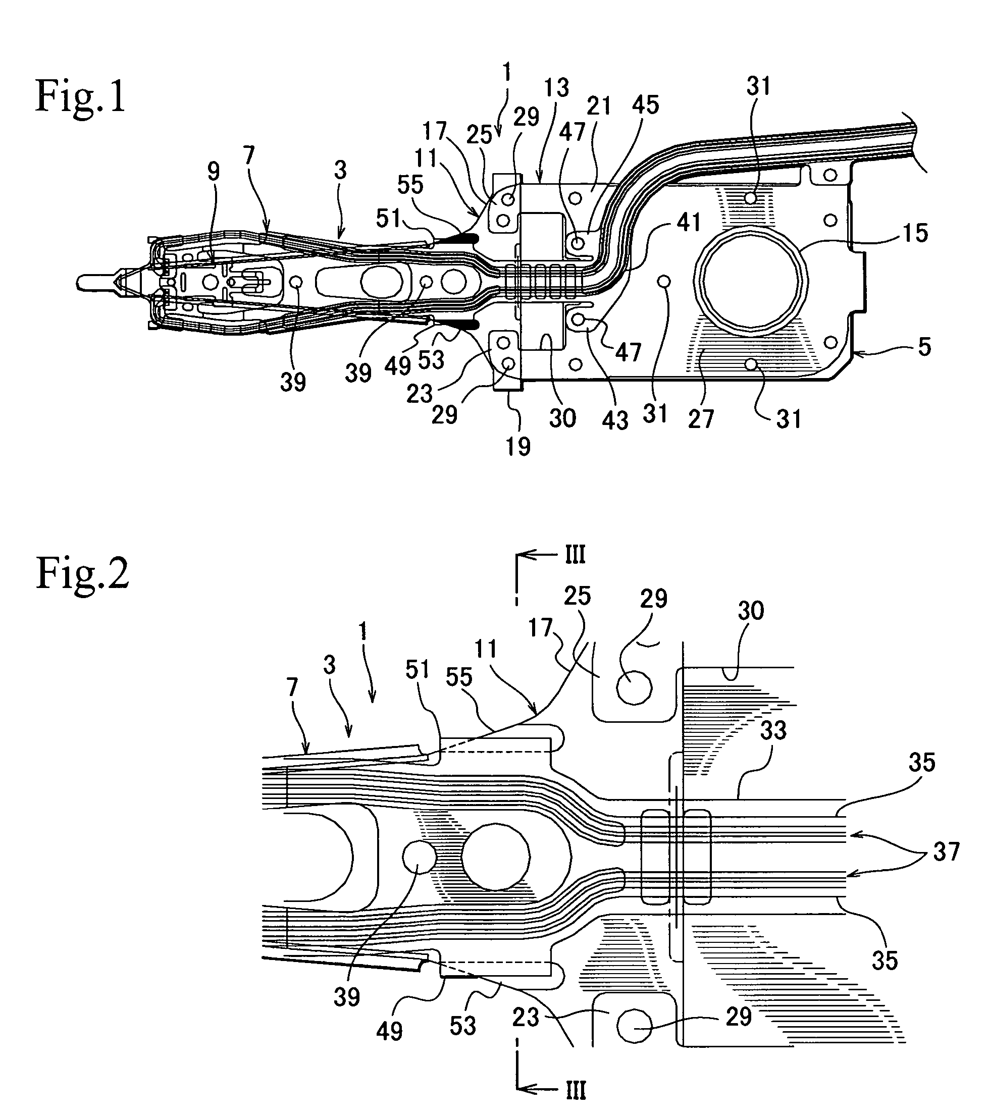
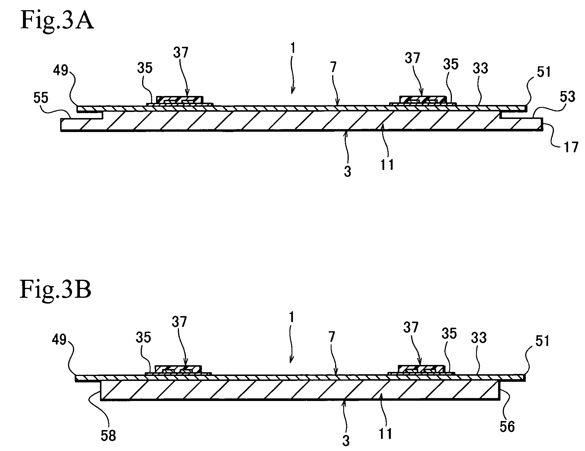
[0028]FIG. 1 is a partially transmissive plan view showing a head suspension according to a first embodiment of the present invention, FIG. 2 is an enlarged plan view partly showing the head suspension of FIG. 1, and FIG. 3A is a sectional view taken along a line III-III of FIG. 2.

[0029]A head suspension 1 shown in FIGS. 1 to 3 is provided with a load beam 3, a base plate 5 corresponding to a base, a flexure 7, and the like.

[0030]The load beam 3 applies load onto a head 9 that is arrange at a front end of the load beam 3 to write and read data to and from a disk arranged in the hard disk drive. The load beam 3 includes a rigid part (beam, or flange portion) 11 and a resilient part (or hinge) 13.

[0031]The base plate 5 has a rectangular plate shape. The base plate 15 includes a boss 15. The boss 15 is attached by swaging or the like to an arm of a carriage installed in a hard disk ...

second embodiment

[0047]FIG. 4 is an enlarged plan view partly showing a main portion of a head suspension according to a second embodiment of the present invention. The structure of the second embodiment is basically the same as that of the first embodiment, and therefore, the same or corresponding parts are represented with the same reference numerals or the same reference numerals plus “A.”

[0048]According to a head suspension 1A of the embodiment, a recessed portion 57 for avoiding vibration contact of the curved portion 41 of the flexure 7 is provided in the base plate 5 side.

[0049]As described above, the flexure 7 has the curved portion 41 curving sideward on the base plate 5, and the recessed portion 57 corresponds to the curved portion 41. The recessed portion 57 is formed at a central portion of the base plate 5 side in an across-the-with direction thereof such that a length of the recessed portion 57 is distributed approximately equally in the across-the-with direction regarding the central ...


PUM

PropertyMeasurementUnit
thicknessaaaaaaaaaa
thicknessaaaaaaaaaa
thicknessaaaaaaaaaa

Abstract

A head suspension for a hard disk drive has a base attached to a carriage of the hard disk drive and is turned around a spindle. A load beam includes a rigid part and a resilient part which applies load onto a head at a front end of the load beam to write and read data to and from a disk arranged in the hard disk drive. The rigid part is supported to the base through the resilient part. A flexure is attached to at least the rigid part of the load beam and has read / write wiring patterns connected to the head. A recessed portion or a through-hole portion is formed in at least one of the load beam and the base for avoiding vibration contact of the flexure.

Description

BACKGROUND OF THE INVENTION[0001]1. Field of the Invention[0002]The present invention relates to a head suspension for a hard disk drive incorporated in an information or data processing apparatus such as a computer.[0003]2. Description of the Related Art[0004]In general, a head suspension for a hard disk drive includes a base plate, a load beam extending from the base plate toward a head, a flexure, and the like. The load beam is conventionally made of a stainless steel such as SUS304 or SUS301 (Japanese Industrial Standard) with a plate thickness of about 20 μm to 100 μm. The flexure is conventionally formed by applying an insulating material layer (polyimide) and an electrically conductive layer (copper) on a base material made of a stainless steel plate (SUS304) with a plate thickness of 20 μm or a proper resilient material using a laminating process or a usual photolithographic process.[0005]FIG. 5 shows a chain product of flexures. The chain product has a plurality of flexures...

Claims


Application Information

Patent Timeline
Patent Type & Authority Patents(United States)
IPC IPC(8): G11B5/55
CPCG11B5/4833
Inventor OGAWA, HIDENORIANDO, TOSHIKI
Owner NHK SPRING CO LTD
Learn More