Cylinder characteristic variation sensing device

a sensing device and characteristic variation technology, applied in the direction of electrical control, process and machine control, instruments, etc., can solve the problems that the output torque and the emission state of the internal combustion cannot be controlled with high accuracy, and achieve high accuracy, high accuracy, and high accuracy

Active Publication Date: 2010-03-16
DENSO CORP
View PDF9 Cites 21 Cited by
  • Summary
  • Abstract
  • Description
  • Claims
  • Application Information

AI Technical Summary

Benefits of technology

[0016]According to the above-described aspect of the present invention capable of sensing the cylinder characteristic variation in this way, variation amounts of the cylinder characteristics of the respective cylinders can be calculated and learned, for example. The injection quantity variation can be calculated based on the actual injection quantities of the respective cylinders sensed with the injection quantity sensing section, and the calculation results can be learned. Thus, the cylinder characteristic variation and the injection quantity variation can be learned separately. For example, by changing control contents of the injection mode (such as the injection quantity, injection timing, and the number of injection stages in the case of multi-stage injection) based on the learning result, the output torque and the emission state of the internal combustion can be controlled with high accuracy.
[0034]The fixing structure of the fuel pressure sensor can be simplified in the case where the fuel pressure sensor is fixed to the fuel inlet as compared with the case where the fuel pressure sensor is mounted inside the injector. When the fuel pressure sensor is mounted inside the injector, the fixing position of the fuel pressure sensor is closer to the injection hole of the injector than in the case where the fuel pressure sensor is fixed to the fuel inlet. Therefore, the pressure fluctuation in the injection hole can be sensed more appropriately.

Problems solved by technology

Therefore, the output torque and an emission state of the internal combustion cannot be controlled with high accuracy.

Method used


Image

  • Cylinder characteristic variation sensing device
  • Cylinder characteristic variation sensing device
  • Cylinder characteristic variation sensing device

Examples


Embodiment Construction

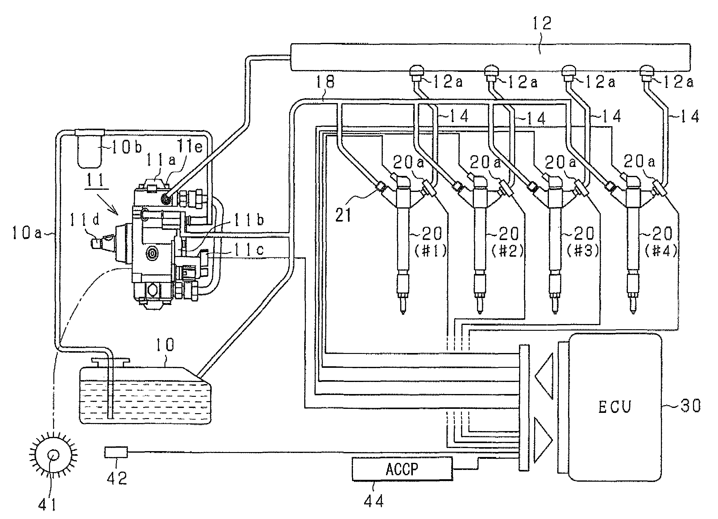
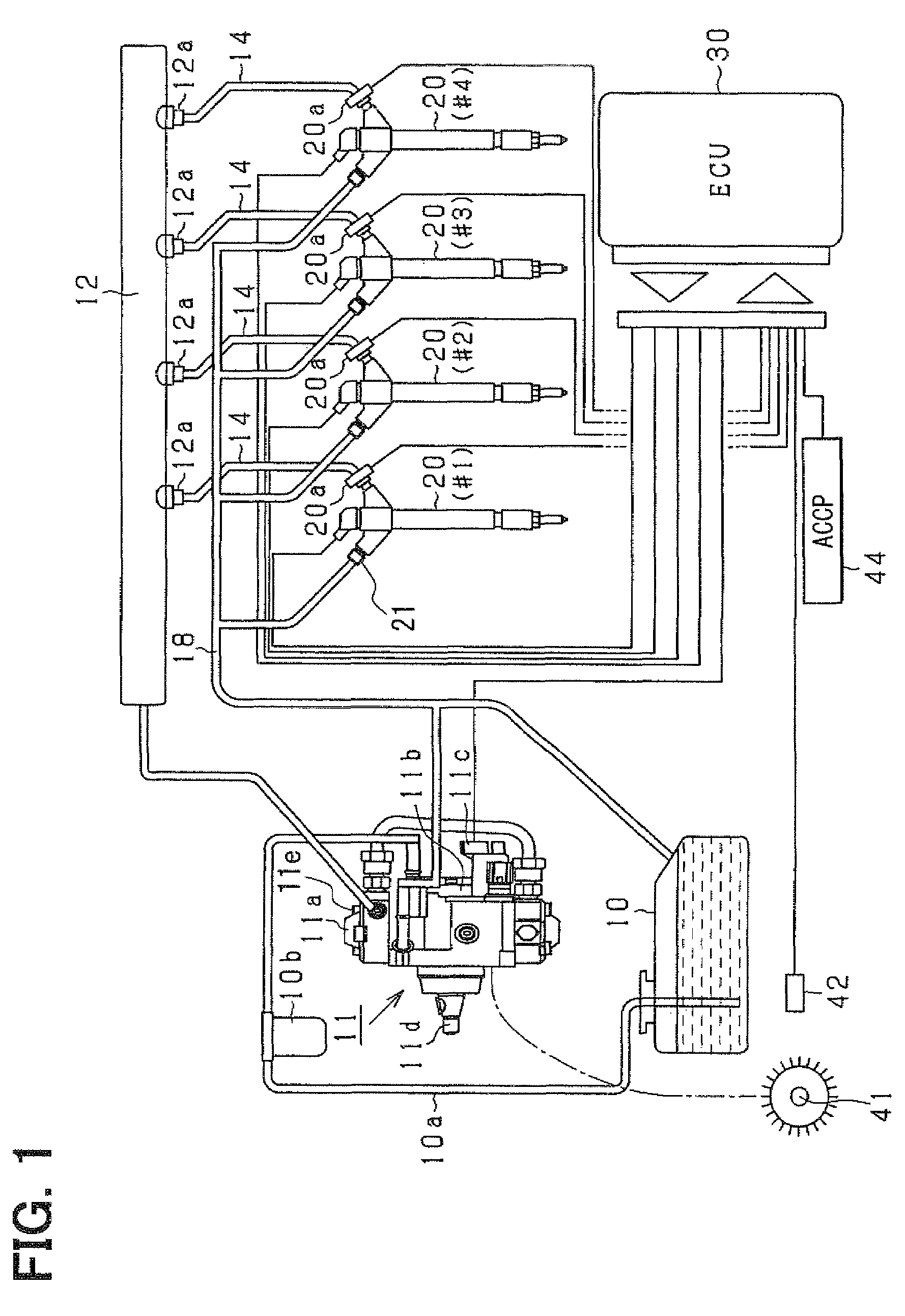
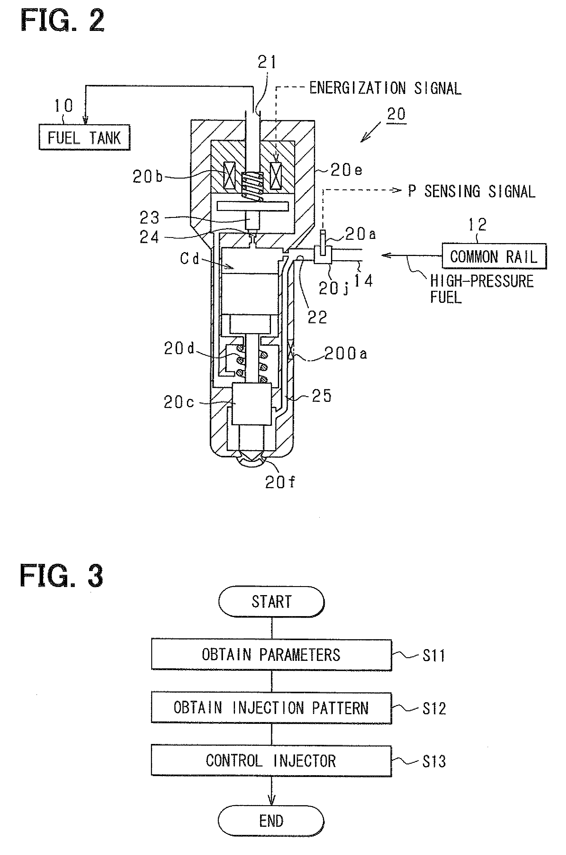
[0047]Hereafter, an embodiment of the present invention will be described with reference to the drawings. First, an outline of an engine (an internal combustion engine) having an internal combustion engine control device according to the present embodiment will be explained briefly.

[0048]The device according to the present embodiment is used for a diesel engine (an internal combustion engine) for a four-wheeled vehicle. The engine performs injection supply (direct injection supply) of high-pressure fuel (for example, light oil at injection pressure of 1000 atmospheres or higher) directly into a combustion chamber. It is assumed that the engine according to the present embodiment is a four-stroke reciprocating diesel engine (an internal combustion engine) having multiple cylinders (for example, in-line four cylinders). In each of the four cylinders #1 to #4, a combustion cycle consisting of four strokes of an intake stroke, a compression stroke, a combustion stroke, and an exhaustion...


PUM


Abstract

A cylinder characteristic variation sensing device has a small injection controlling section that performs small injections sequentially in respective cylinders, a torque increase amount sensing section that senses an increase amount of output torque caused in connection with the small injection for each cylinder, an injection quantity sensing section that senses an actual injection quantity of the small injection for each cylinder, and a cylinder characteristic variation calculating section that calculates a variation in a cylinder characteristic among the cylinders (i.e., a cylinder characteristic variation) based on a variation in the sensing value of the injection quantity sensing section among the cylinders (i.e., an injection quantity variation) and a variation in the sensing value of the torque increase amount sensing section among the cylinders (i.e., a torque increase amount variation).

Description

CROSS REFERENCE TO RELATED APPLICATION[0001]This application is based on and incorporates herein by reference Japanese Patent Application No. 2007-279638 filed on Oct. 26, 2007.BACKGROUND OF THE INVENTION[0002]1. Field of the Invention[0003]The present invention relates to a cylinder characteristic variation sensing device that senses a variation among characteristics of respective cylinders of a multi-cylinder internal combustion engine.[0004]2. Description of Related Art[0005]Conventionally, FCCB correction for correcting fuel injection quantities of the respective cylinders is known as correction for smoothing a variation in an injection quantity among cylinders (i.e., an injection quantity variation) caused by individual differences and aging degradation of injectors provided in the respective cylinders and the like in a multi-cylinder internal combustion engine (for example, refer to Patent document 1: JP-A-2001-355500). In the FCCB correction, sensing values of rotation speed ...

Claims


Application Information

Patent Timeline
Patent Type & Authority Patents(United States)
IPC IPC(8): G01M15/04
CPCF02D41/1498F02D41/2438F02D41/247F02D41/403F02D41/12F02D2250/04Y02T10/44Y02T10/40
Inventor ISHIZUKA, KOJINAKATA, KENICHIRO
Owner DENSO CORP
Why Eureka
Try Eureka