Supercharge Your Innovation With Domain-Expert AI Agents!

Navigation light system using spatially separated partial arc navigation running lights

a navigation light and partial arc technology, applied in the direction of lighting and heating equipment, transportation and packaging, lighting support devices, etc., can solve the problems of occlusion, or occlusion, undesirable process, and occlusion of beams, so as to avoid occlusion, the effect of occlusion

Inactive Publication Date: 2010-03-16
WOLSKE JAMES P VON
View PDF40 Cites 6 Cited by
  • Summary
  • Abstract
  • Description
  • Claims
  • Application Information

AI Technical Summary

Benefits of technology

[0020]One problem with prior art lights is glare. Excessive glare is usually caused by the placement of a navigation light somewhat centrally located in the boat such that fugitive light casts downward into the cockpit and deck areas of the boat and tends to adversely affect the boat operators ability to see at night. Excessive glare is also caused when the intended and outwardly directed light beam strikes objects or people on the subject boat. In either case, excessive glare is undesirable because it impairs the boat operator's ability to see into the darkness of night as part of his requirement to “maintain proper lookout”. Glare can be reduced or eliminated by proper placement of spatially separated, piecewise continuous, partial arc white lights.

Problems solved by technology

Some occlusion is permitted, but it is undesirable.
Occlusion, or occluding is the undesirable process whereby the beam of light is blocked from its desired or otherwise intended outward path by striking parts of the boat or people that are standing in the way of the light beam.
Occlusion of the beam is detrimental to both the operators of the boat and to distant observers of the boat.
It is detrimental to the operators of the boat because the light striking the occluding object reflects back towards the operator and causes glare in his eyes that reduces his night vision capability.
It is also detrimental to a distant observer of the subject boat because the allowed occlusion obliterates the very same light that the distant observer needs to see in order to inform him of the presence of the subject boat and take necessary evasive action.
Occlusion and glare are often the unavoidable result of using only one light centrally located on the boat and is a common problem on most boats.
Even the use of two lights as directed by the Navigation Rules causes glare and occlusions.
The precision of the arithmetic is unfortunate because it forces the designers of these lights to direct their attention to a falsely precise number and often disregard the consequences of glare and occlusion.
Rigorous pursuit of such minutia often leaves unsolved the larger issues of visual safety as it relates to conspicuity and proper lookout.
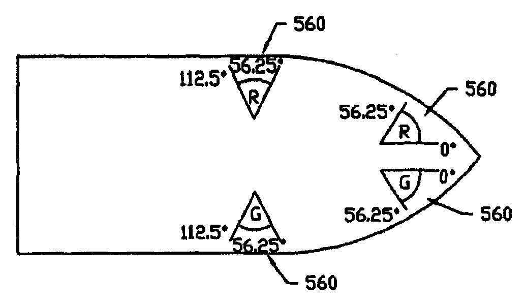
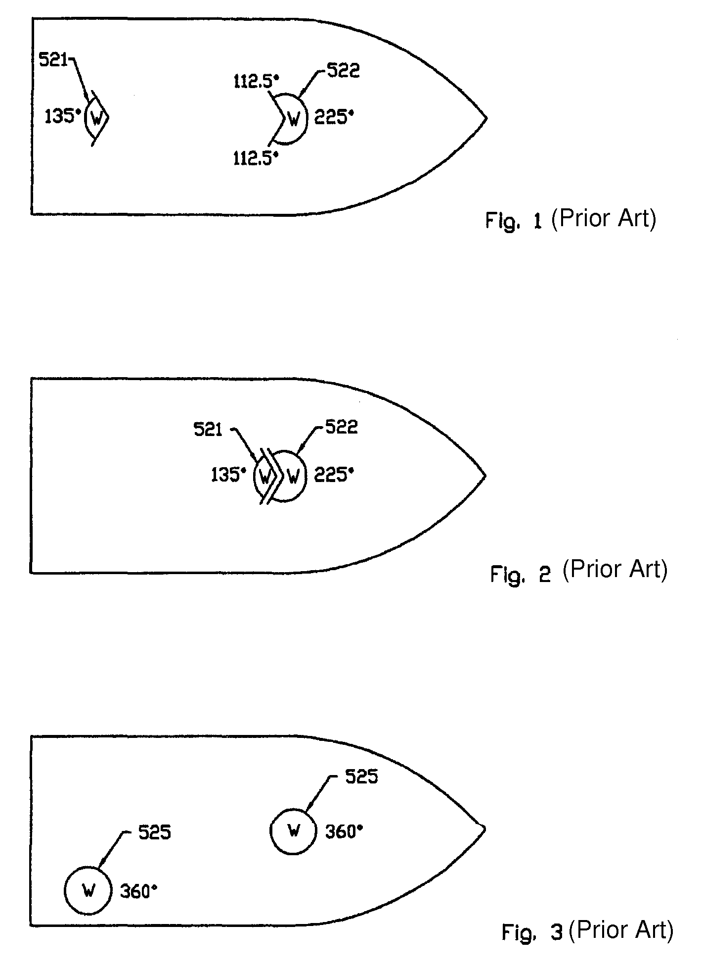
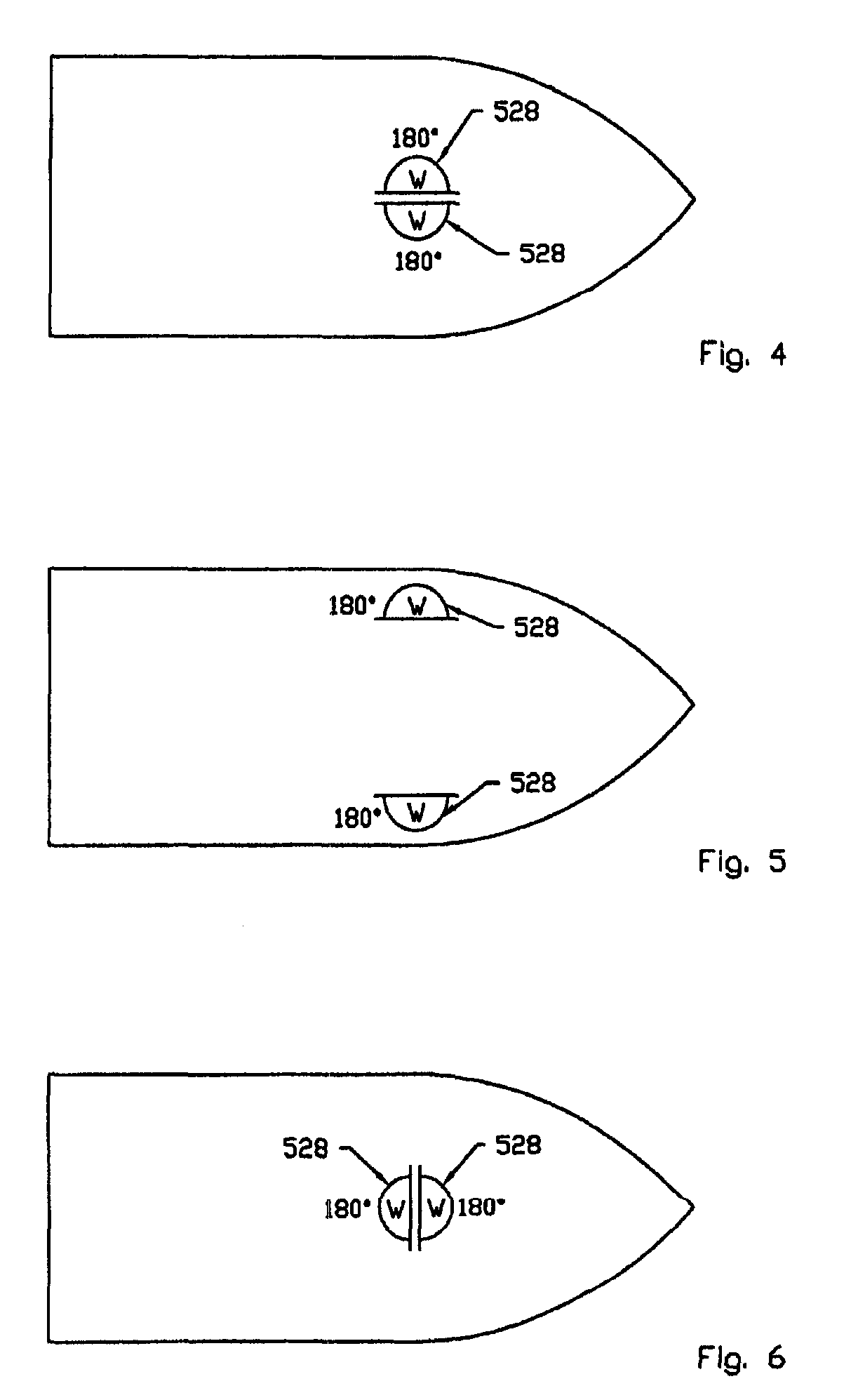
Although the Navigation Rules show single fixtures, there is no real valid scientific basis as to why these different lights cannot be configured differently and still be optically equivalent to the original standard as prescribed by the Navigation Rules.
Conversely, two spatially merged points of light cannot be rotated to appear to be visually separated.
All types of glare are detrimental to an operator's ability to see.
Secondary glare is the source of much of the glare problem associated with navigation light installation and operation.
Fog is a primary cause of bloom.
Fugitive light is any light that goes where it is not wanted and usually causes harmful glare.
This harmful glare impairs an operator's ability to see.
However, it would be counterproductive to make the navigation lights so bright that they excessively contribute to the glare problem and thus impair the operator's ability to see.
These limits prohibit the use of docking lights and spotlights while normally operating on the water.
However, these limits do allow the non-steady use of searchlights that are manually controllable and do not present a continuous blinding effect to an oncoming boat.
There is also a practical limit on the maximum brightness because if a light is too bright, it tends to cause too much glare to the operator and it uses an excess of power.
The physiology of the eyeball is such that even very low levels of light in a person's field of vision, even in the periphery, cause a severe reduction in the ability to see in the darkness.
One problem with prior art lights is glare.
Excessive glare is usually caused by the placement of a navigation light somewhat centrally located in the boat such that fugitive light casts downward into the cockpit and deck areas of the boat and tends to adversely affect the boat operators ability to see at night.
Excessive glare is also caused when the intended and outwardly directed light beam strikes objects or people on the subject boat.
In either case, excessive glare is undesirable because it impairs the boat operator's ability to see into the darkness of night as part of his requirement to “maintain proper lookout”.
The problem with glare is so severe that it causes some boaters to shut off their lights while running at night.
Even though this practice is illegal and dangerous, it is a risk taken by the operator who is desperate to eliminate glare.
This intentional occlusion of the light is dangerous because a neighboring boat directly ahead cannot see the subject boat.
A second problem with prior art lights is occlusion.
Thus, the subject boat cannot be seen at all times from all angles and therefore does not meet the requirement to “maintain proper conspicuity”.
Whether the light is incandescent or LED or any other source, it is the wide angle of divergence of the beam spread of prior art lights combined with a bad location of the light fixture that causes glare on the boat and appurtenances.
This high location renders the light rather ineffective because, by nature, people look at the horizon for danger.
A light located high on a mast is suitable for high seas operation, but is less than ideal for use on inland lakes surrounded by hills or high banks.
Prior art does not give suitable close proximity warning to an approaching boat.

Method used


Image

  • Navigation light system using spatially separated partial arc navigation running lights
  • Navigation light system using spatially separated partial arc navigation running lights
  • Navigation light system using spatially separated partial arc navigation running lights

Examples


Embodiment Construction

[0070]The following description is presented to enable one of ordinary skill in the art to make and use a navigation light system according to the present invention as provided within the context of a particular application and its requirements. Various modifications to the preferred embodiment will, however, be apparent to one skilled in the art, and the general principles defined herein may be applied to other embodiments. Therefore, a navigation light system according to the present invention is not intended to be limited to the particular embodiments shown and described herein, but is to be accorded the widest scope consistent with the principles and novel features herein disclosed.

[0071]A navigation light system according to various embodiments of the present invention uses multiple partial arc lights (placed near the perimeter) to minimize glare. The navigation lights described herein use multiple partial arc lights (placed near the perimeter) to minimize occlusion. A navigati...


PUM


Abstract

A navigation light system for a watercraft including multiple lights of a common color and that are spatially separated on the watercraft to collectively operate as a navigation running light that has a specified horizontal beam sector of less than 360 degrees. Each light is separately masked to emit light outwardly from the watercraft within a partial arc horizontal beam sector which is less than the specified horizontal beam sector. The navigation light system may include first and second running lights of first and second colors, respectively, where each running light includes multiple commonly-colored lights that are separately masked within a corresponding one of mutually exclusive partial arc horizontal beam sectors within the specified horizontal beam sector.

Description

CROSS-REFERENCE TO RELATED APPLICATIONS[0001]This application claims the benefit of U.S. Provisional Application Ser. No. 60 / 706,364, filed on Aug. 8, 2005, which is herein incorporated by reference for all intents and purposes.[0002]This application is a continuation-in-part of U.S. patent application Ser. No. 10 / 663,899 entitled “A Docking Light System Including An Accessory Lamp” having a common inventor, which is itself a divisional application of U.S. patent application Ser. No. 09 / 982,322 entitled “Navigation Light System and Method” filed Oct. 18, 2001, having a common inventor and now issued as U.S. Pat. No. 6,637,915, both of which being hereby incorporated by reference in their entireties for all intents and purposes:BACKGROUND OF THE INVENTION[0003]1. Field of the Invention[0004]The present invention is directed towards a navigation light system for watercraft, and more particularly towards a navigation light system that employs spatially separated partial arc lights whic...

Claims


Application Information

Patent Timeline
IPC IPC(8): F21V1/00
CPCB63B45/00B63B45/04B63B45/02F21V21/30
Inventor WOLSKE, JAMES P. VON
Owner WOLSKE JAMES P VON
Features
  • R&D
  • Intellectual Property
  • Life Sciences
  • Materials
  • Tech Scout
  • Unparalleled Data Quality
  • Higher Quality Content
  • 60% Fewer Hallucinations
Learn More