
Sealant drawing method, sealant drawing apparatus, and method and apparatus for manufacturing liquid crystal device

a technology of sealant and drawing apparatus, which is applied in the direction of liquid surface applicators, instruments, coatings, etc., can solve the problems of screen printing method, difficult uniform discharge of sealant having a high viscosity, and non-conformity, etc., to achieve high quality display, improve productivity, and reduce cost

Inactive Publication Date: 2010-03-16
138 EAST LCD ADVANCEMENTS LTD
View PDF12 Cites 0 Cited by
  • Summary
  • Abstract
  • Description
  • Claims
  • Application Information

AI Technical Summary

Benefits of technology

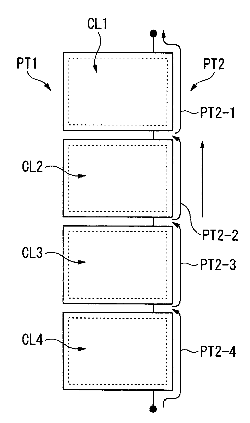
"The invention provides a sealant drawing method and apparatus that can efficiently and stably perform sealant drawing with a simplified control system. This method can achieve a uniform cell gap even when using high-viscosity sealant, and it can be performed in a batch manner to reduce the amount of sealant needed. The method also reduces the variation in viscosity and discharge amount of the sealant, simplifies the operation of the coating unit, and improves productivity. The method includes forming patterns for sealing on multiple panel formation regions on a substrate, and the formation of the patterns can be performed in opposite directions to prevent the formation of drawing pools and ensure a desired cell gap. The method also includes calculating coordinate values for each panel formation region before discharging the sealant, which further simplifies the process."

Problems solved by technology

However, the screen-printing method is problematic in that nonconformity sometimes occurs since the screen is brought in contact with the inner surface of the substrate.
Furthermore, in a method of pushing out sealant by means of air pressure, it is difficult to uniformly discharge sealant having a high viscosity.
In the case of manufacturing a liquid crystal device by drawing sealant having a high viscosity, as in JP-A-2004-290885, however, if the drawing start position and the drawing end position of the sealant overlap each other, a defective cell gap is likely to occur due to the thickness of the sealant.
Therefore, it is difficult to draw the sealant in a short period of time.
Therefore, since discharging and non-discharging of the sealants are continuously generated, it becomes difficult to stably flow the sealants within the coating unit, which may lead to variation in the amount of sealant that is discharged.
In addition, since the coating unit has to be scanned on a first basic material or a second basic material, the operation of the coating unit becomes complicated.
In addition, if such a drawing gathering phenomenon is generated between a panel formation region and a counter substrate opposite to the panel formation region, a predetermined cell gap cannot be obtained when the panel formation region and the counter substrate are adhered.

Method used


Image

  • Sealant drawing method, sealant drawing apparatus, and method and apparatus for manufacturing liquid crystal device
  • Sealant drawing method, sealant drawing apparatus, and method and apparatus for manufacturing liquid crystal device
  • Sealant drawing method, sealant drawing apparatus, and method and apparatus for manufacturing liquid crystal device

Examples


Embodiment Construction

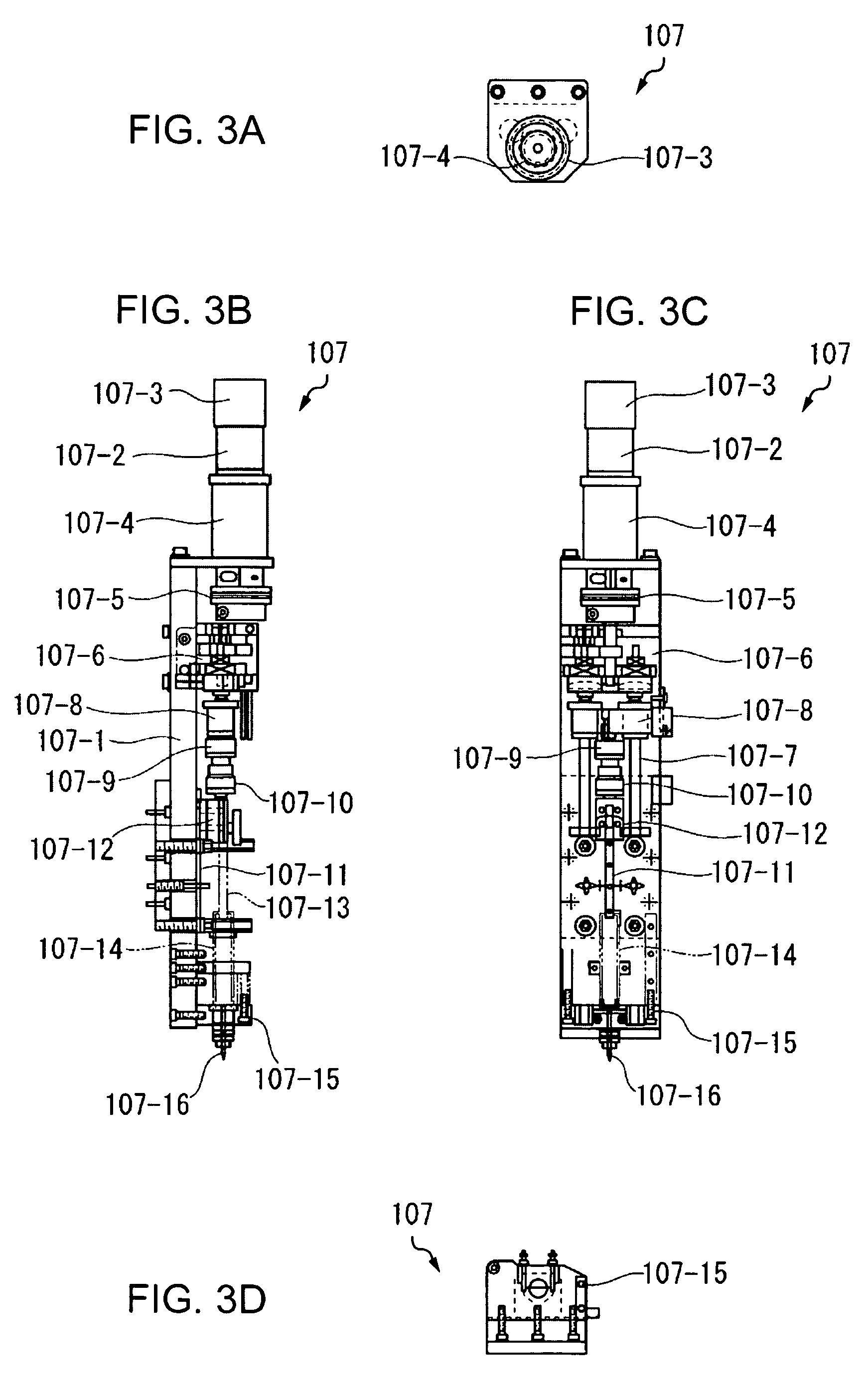
[0051]Hereinafter, a sealant drawing method, a sealant drawing apparatus, and a method and apparatus for manufacturing liquid crystal devices according to the invention will be described in detail in connection to embodiments with reference to the accompanying drawings.

Sealant Drawing Apparatus

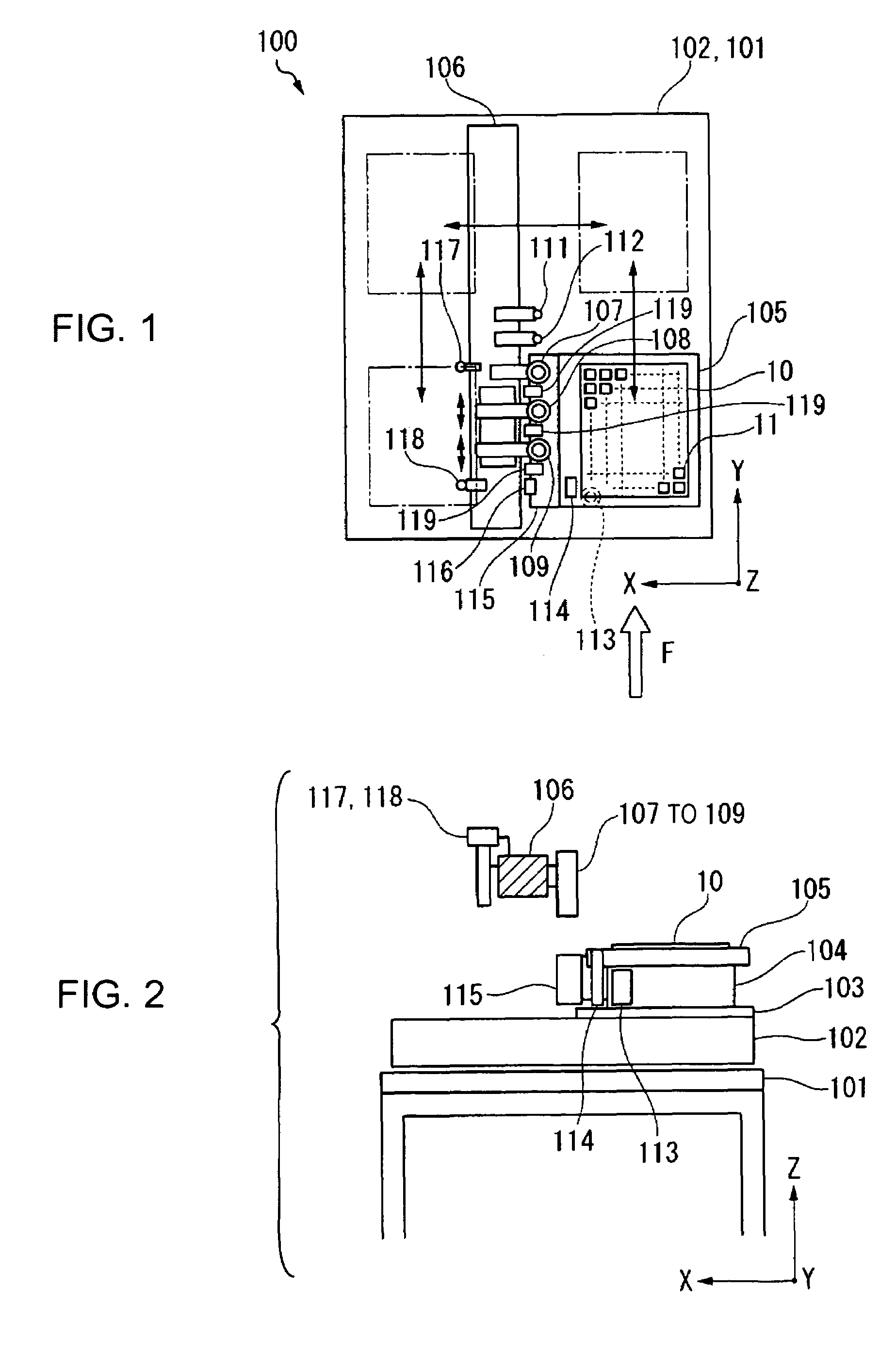
[0052]FIG. 1 is a schematic plan view showing a sealant drawing apparatus (a manufacturing apparatus of a liquid crystal device) according to an embodiment of the invention. FIG. 2 is a schematic explanatory view showing the arrangement construction of each of the elements of the apparatus in a height direction.

[0053]In the sealant drawing apparatus 100, an XY drive mechanism 102 (movement unit) is fixed to a support frame 101. An XY movement stage 103 (movement unit) is disposed to move on the XY drive mechanism 102 in a horizontal direction (i.e., an X direction and a Y direction). A θ drive mechanism 104 (movement unit) is fixed on the XY movement stage 103. A support table 105, which is ad...


PUM


Abstract

A sealant drawing method is provided in which patterns for sealing an electro-optic material over a plurality of panel formation regions on a substrate are drawn by discharging sealant on the substrate from a nozzle of a coating unit, and which includes forming continuously first patterns on the plurality of panel formation regions in a batch manner, so as to form parts of the individual patterns in the plurality of panel formation regions; and forming continuously second patterns on the plurality of panel formation regions in a batch manner, so as to form the remainders of the individual patterns in the plurality of panel formation regions.

Description

BACKGROUND[0001]1. Technical Field[0002]The present invention relates to a sealant drawing method, to a sealant drawing apparatus, and to a method and apparatus for manufacturing liquid crystal devices, and in particular, to a manufacturing technology suitable to a case where sealant with a high viscosity is used.[0003]2. Related Art[0004]In general, in the process of manufacturing liquid crystal devices, a panel structure in which two substrates are adhered together using sealant and a liquid crystal material is enclosed therebetween is constructed. This manufacturing process includes a sealant coating process of forming a liquid crystal material enclosure region that contains a liquid crystal material by coating the sealant in such a way as to surround electrode patterns, such as transparent electrodes formed on an inner surface of the substrate. In the sealant coating method in this process, a screen-printing method has been widely used, especially, in the case where sealant havi...

Claims


Application Information

Patent Timeline
Patent Type & Authority Patents(United States)
IPC IPC(8): B05D5/12
CPCG02F1/1339H01L21/67126G02F1/133351
Inventor MURAKAMI, CHIHIRO
Owner 138 EAST LCD ADVANCEMENTS LTD
Learn More