
Switching device

a technology of switching device and electrical contact, which is applied in the direction of air-break switch, high-tension/heavy-dress switch, electrical apparatus, etc., can solve the problem achieve the effect of reducing the contact resistance of electrical contact, reducing mechanical loadability and mechanical endurance of electrical contact points, and improving mechanical loadability and mechanical enduran

Inactive Publication Date: 2010-03-16
SIEMENS AG
View PDF14 Cites 8 Cited by
  • Summary
  • Abstract
  • Description
  • Claims
  • Application Information

AI Technical Summary

Benefits of technology

"The invention is about a switching device that can withstand high mechanical and thermal loads while still maintaining good electrical contact. The design uses an arc-resistant material that is electroplated, which helps to reduce contact resistance and prevent oxidation. The arc-resistant material is fixed to the hollow-cylindrical basic body in the form of a ring, which increases the stability of the device against switching arcs. The ring can be pressed against the basic body using a bolt connection or a pressure element, and an insulating body can be added to further improve stability. The design also allows for a reduction in wall thickness of the ring, which makes it easier to assemble and reduces the mass of the device. Overall, the invention provides a switching device that is more robust and reliable."

Problems solved by technology

This reduces the contact resistance of the electrical contact.

Method used


Image

  • Switching device
  • Switching device
  • Switching device

Examples


Embodiment Construction

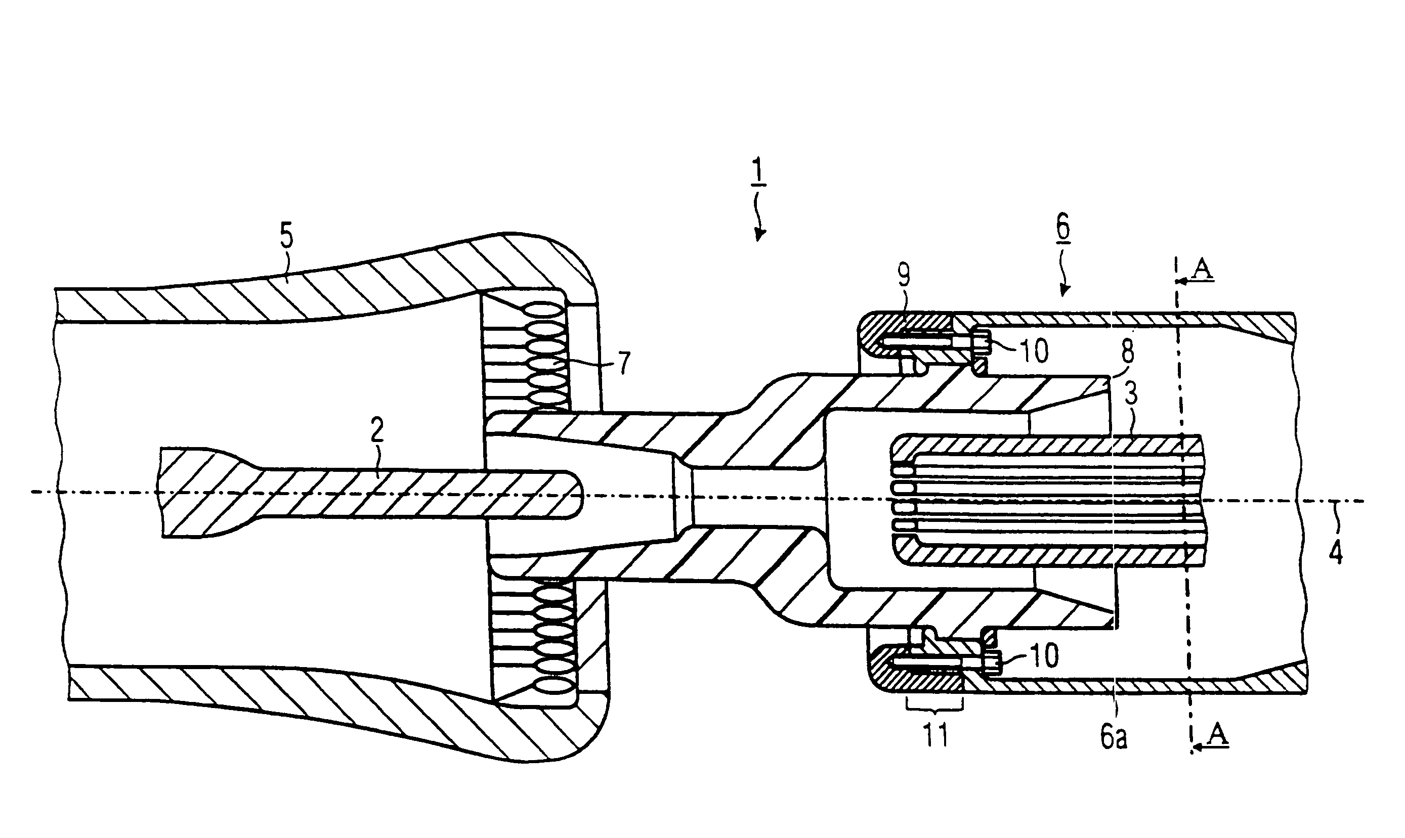
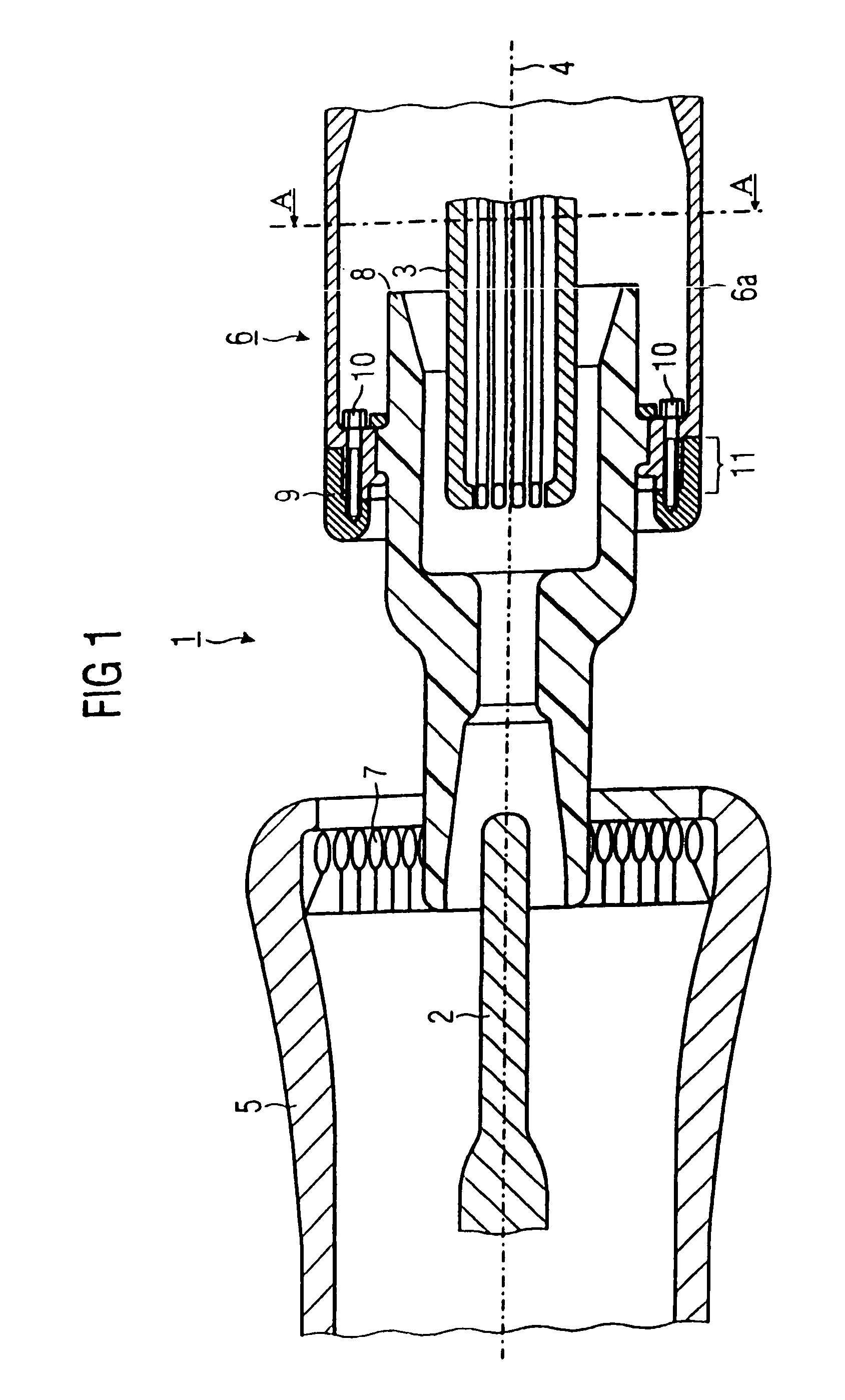
[0025]The switching device illustrated in FIG. 1 is a high-voltage power breaker 1. A high-voltage power breaker 1 is used to switch rated currents and short-circuit currents. The high-voltage power breaker 1 has a first arcing contact piece 2 and a second arcing contact piece 3. The first arcing contact piece 2 is essentially cylindrical and has a coating of an arc-resistant material at its end facing the switching path of the high-voltage power breaker 1. The second arcing contact piece 3 is in the form of a tulip contact, in which the first arcing contact piece 2 can be inserted. At its end facing the switching path, the second arcing contact piece 3 likewise has a coating of arc-resistant material. The two arcing contact pieces 2, 3 are arranged axially opposite one another on a main axis 4. A first rated current contact piece 5 is arranged concentrically with respect to the first arcing contact piece 2. A second rated current contact piece 6 is arranged concentrically with resp...


PUM


Abstract

An electrical switching device, especially a high-voltage circuit breaker, contains arcing contacts and nominal current contacts. At least one of the nominal current contacts has a surface formed of an arc-resistant material provided with a galvanic coating. In this configuration, the contact points can withstand high mechanical and thermal loads and at the same time maintain a high current carrying capacity.

Description

BACKGROUND OF THE INVENTIONField of the Invention[0001]The invention relates to a switching device having a first and a second arcing contact piece, which lie axially opposite one another, and a first and a second rated current contact piece, which are arranged coaxially with respect to the arcing contact pieces, at least one of the rated current contact pieces having a hollow-cylindrical basic body; which is covered at the front by an arc-resistant material at its end facing a switching path of the switching device.[0002]Such a switching device has been disclosed, for example, in the European patent application EP 0 982 748 A1. Therein, the arcing contact pieces are covered by an arc-resistant material by means of plasma spraying such that an arc drawn between the arcing contact pieces does not cause any erosion, or only causes a very low amount of erosion. Furthermore, the rated current contact pieces likewise have an erosion-resistant protective coating, which is applied by means...

Claims


Application Information

Patent Timeline
Patent Type & Authority Patents(United States)
IPC IPC(8): H01H9/30H01H11/04H01H33/00
CPCH01H11/041H01H33/00H01H2011/046
Inventor GERICKE, JOACHIMLEHMANN, VOLKERNOWAKOWSKI, ANDRZEJSCHULER, KLAUS
Owner SIEMENS AG
Learn More