Motor control device

a technology of motor control and control device, which is applied in the direction of motor/generator/converter stopper, dynamo-electric gear control, and dynamo-electric converter control. it is not always the optimum choice to switch within a single coordinate system, and it is difficult to accurately estimate the position and speed of the rotor in low-speed rotation or at a standstill

Active Publication Date: 2010-03-16
SANYO ELECTRIC CO LTD
View PDF24 Cites 43 Cited by
  • Summary
  • Abstract
  • Description
  • Claims
  • Application Information

AI Technical Summary

Benefits of technology

[0003]The present invention relates to a motor control device for controlling the operation of a motor. The present invention also relates to a motor drive system incorporating such a motor control device.

Problems solved by technology

With this method, however, it is difficult to accurately estimate the position and speed of the rotor in low-speed rotation or at a standstill.
Moreover, the formula for calculating the specified γ-axis current value iγ* for maximum torque control or the like contains a plurality of motor parameters whose true values are unknown, and thus, if there are errors between the motor parameters (calculation parameters) used to calculate the specified γ-axis current value iγ* and the true motor parameters, it is impossible to perform motor control as desired.
From the perspective of easy adjustment of the operation parameters, reduction of calculation amount, or any other benefit, however, switching within a single coordinate system is not always be the optimum choice.

Method used


Image

  • Motor control device
  • Motor control device
  • Motor control device

Examples


first embodiment

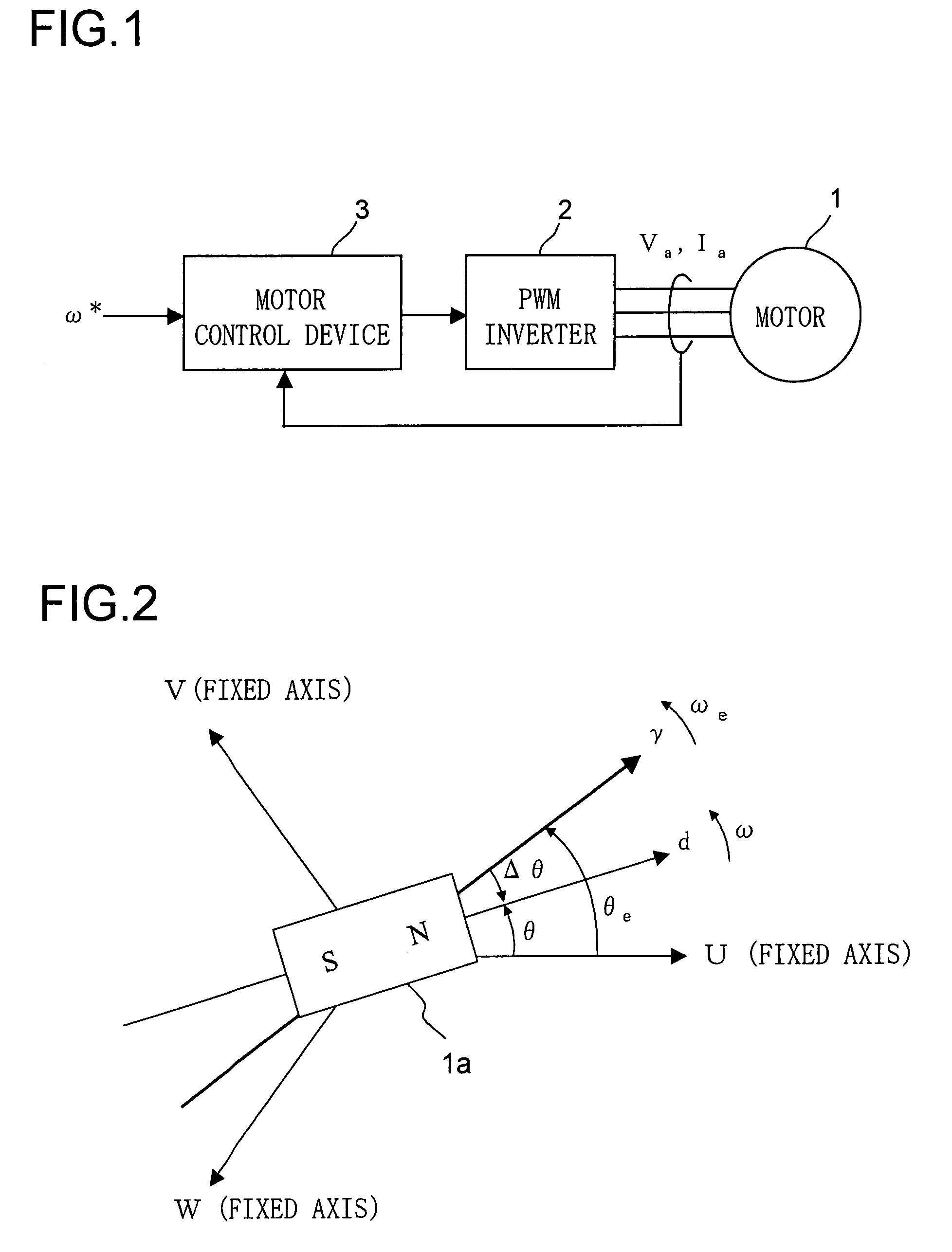
[0076]FIG. 1 is a block configuration diagram of a motor drive system according to a first embodiment of the invention. The reference numeral 1 represents a three-phase permanent-magnet synchronous motor 1 (hereinafter referred to simply as “the motor 1”) that has a permanent magnet on a rotor (unillustrated) and that has an armature winding on a stator (unillustrated). The motor 1 is a salient-pole motor (a motor having a salient pole) as exemplified by an interior permanent magnet synchronous motor.

[0077]The reference numeral 2 represents a PWM (pulse-width modulation) inverter that supplies the motor 1 with three-phase alternating-current voltages of U-, V-, and W-phases according to the position of the rotor of the motor 1. The voltage supplied to the motor 1 is referred to as the motor voltage (armature voltage) Va, and the current supplied from the PWM inverter 2 to the motor 1 is referred to as the motor current (armature current) Ia.

[0078]The reference numeral 3 represents a...

second embodiment

[0148]Next, a second embodiment of the invention will be described as one involving switching among different control methods—the feature with which one of the main objects of the invention is achieved. Throughout all the embodiments, that is, the first embodiment described above, this embodiment, and the following embodiments described later, unless otherwise described, the same parts are identified by the same reference numerals, and the same values, directions, etc. are identified by the same symbols (such as θ and ω). Accordingly, in principle, no overlapping explanations will be repeated for the parts, values, directions, etc. that bear the same reference numerals and symbols once they have been described.

[0149]FIG. 10 is a block configuration diagram of a motor drive system according to a second embodiment of the invention. The motor drive system according to the second embodiment includes a motor 1, an inverter 2, and a motor control device 3a.

[0150]The motor control device ...

third embodiment

[0224]The switching processor 203 shown in FIG. 15 may be made to function simply as a switch that switches between the first and second input values. Now, an example where the switching processor 203 is made to function as a switch will be described as a third embodiment of the invention. All the description of the second embodiment applies also to this embodiment unless inconsistent.

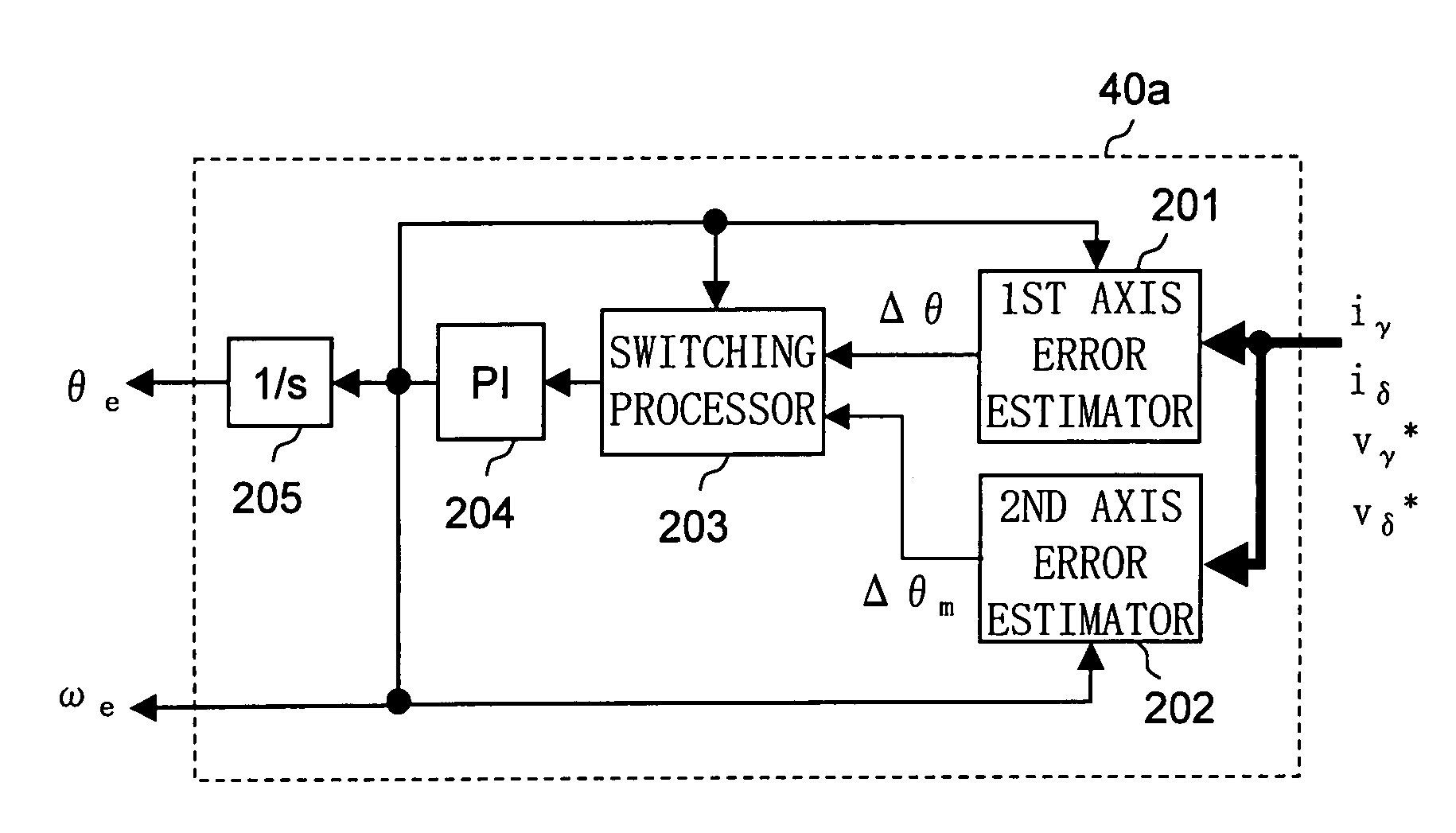
[0225]FIG. 19 is an internal block diagram of the position / speed estimator 40b (hereinafter referred to simply as “the estimator 40b”) according to the third embodiment. In the estimator 40b, the switching processor functions as a switch. The switching processor in the estimator 40b is called the switching processor 203a. The switching processor 203a provides an example of the configuration of the switching processor 203. The estimator 40b can be used as the estimator 40 shown in FIG. 14.

[0226]The estimator 40b shown in FIG. 19 differs from the estimator 40a shown in FIG. 15 in that the switching proce...


PUM


Abstract

Let the rotating axis whose direction coincides with the direction of the current vector that achieves maximum torque control be called the qm-axis, and the rotating axis perpendicular to the qm-axis be called the dm-axis. A motor control device switches its operation between low-speed sensorless control and high-speed sensorless control according to the rotation speed of the rotor. In low-speed sensorless control, the magnetic salient pole of the motor is exploited, and the d-q axes are estimated by, for example, injection of a high-frequency rotating voltage. In high-speed sensorless control, the dm-qm axes are estimated based on, for example, the induction voltage produced by the rotation of the rotor. During high-speed sensorless control, the γ(dm)-axis current is kept at zero irrespective of the δ(qm)-axis current.

Description

[0001]This nonprovisional application claims priority under 35 U.S.C. §119(a) on Patent Application No. 2006-177989 filed in Japan on Jun. 28, 2006, the entire contents of which are hereby incorporated by reference.BACKGROUND OF THE INVENTION[0002]1. Field of the Invention[0003]The present invention relates to a motor control device for controlling the operation of a motor. The present invention also relates to a motor drive system incorporating such a motor control device.[0004]2. Description of Related Art[0005]There have conventionally been developed motor control devices (position-sensorless control devices) that estimate the rotor position of a motor without the use of a rotor position sensor and controls the motor based on the so estimated rotor position. Sensorless control performed in such motor control devices divides into high-speed sensorless control suitable for a motor in high-speed rotation and low-speed sensorless control suitable for a motor in low-speed rotation or ...

Claims


Application Information

Patent Timeline
Patent Type & Authority Patents(United States)
IPC IPC(8): H02P21/14H02P6/16H02P6/06H02P6/08H02P6/17H02P6/28H02P21/00H02P21/13H02P21/18H02P21/22H02P21/24H02P21/28H02P23/12H02P23/14H02P23/16H02P23/18H02P27/04
CPCH02P21/0039H02P21/14H02P2203/05H02P2203/11H02P2207/05H02P21/24
Inventor TOMIGASHI, YOSHIO
Owner SANYO ELECTRIC CO LTD
Why Eureka
Try Eureka